
Slotted PVC pipes retain unslotted ends and solid sections because different parts of the pipe perform different jobs. Openings admit fluid where entry is wanted, while uncut regions can accommodate joints, preserve material around connections or provide a solid conveyance section. A useful pipe layout therefore defines where openings belong, rather than treating every available surface as a place to add slots.
A short blank end on a screen, an uncut band within a slot pattern and a separate length of solid well casing are not the same feature. This article follows those distinctions through several application scenarios. It explains their functions without prescribing a universal end allowance or well construction detail.
How Can One Pipe Be Divided Into Different Functional Zones?
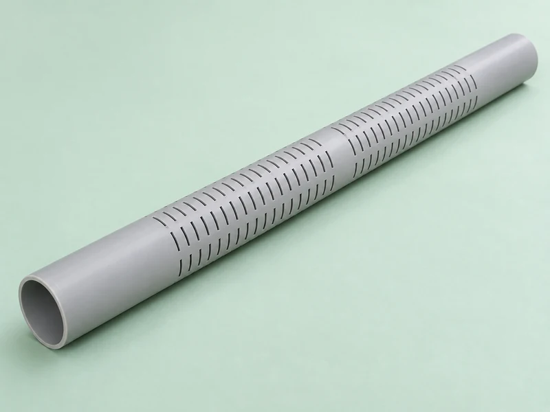
A simple slotted component may have three zones: an uncut connection region, an active slotted region and another uncut end. More complex products can divide the active region into groups separated by solid bands. The pipe drawing determines how these zones relate to each other.
Consider a conceptual pipe laid horizontally on a workbench. The slots are visually prominent, but the plain areas are equally deliberate. They provide space for features and functions that would be compromised if cutting continued uninterrupted to the end.
- Blank end: a local uncut length near a pipe end or joint.
- Solid band: an uncut region separating groups of openings.
- Blank casing: a solid pipe section used as part of a larger assembly.
- Active screen: the section through which fluid is intended to enter.
Manufacturing those boundaries is part of producing a defined pattern. The Yuyu pipe slotting machine range provides the equipment context, while the product design defines where the slotting operation begins, pauses and ends.
Scenario One: Why Leave Material Around a Connection?
An uncut end reserves material and space for the chosen joint. Depending on the design, that region may receive a socket, threads, a coupling or another connection detail. Extending slots into it can interfere with geometry that serves a different purpose from fluid entry.
What Does a Blank End Contribute to a Threaded Joint?
A threaded connection requires a continuous path for the intended thread form. Slots crossing that path would remove portions of the material through which engagement occurs. Leaving an uncut region allows the thread and the screen pattern to occupy separate parts of the component.
The appropriate reserve is not simply the visible thread length. The complete connection may include a shoulder, sealing feature, tool clearance or transition. Those features must be defined together rather than fitted into whatever length happens to remain after slotting.
This is a geometric explanation, not a claim that any uncut end has adequate joint strength. Material, wall section, thread form and loading remain relevant. A blank region makes room for the connection; it does not independently establish its performance rating.
Why Can a Socket or Coupling Need a Different End Layout?
A socket joint engages a length of pipe rather than a single line at the mouth. The intended contact and sealing region may therefore extend farther than it appears from the outside. Keeping slots outside that region preserves the separation between the receiving joint and the active screen.
A shared outside diameter therefore tells the designer little about the required uncut length: that reserved space also has to accommodate the particular joint built into each product. Their joints may use different engagement geometries even if their central slot pattern is identical. The end reserve must follow the connection geometry, so transferring a dimension from an unrelated joint can leave either unnecessary blank material or too little room for engagement.
The relevant socket geometries are introduced in our guide to different socket types. For a combined slotted and socketed product, the end-forming region and cutting region must be planned as parts of the same component.
Scenario Two: Why Is Only Part of a Well Assembly Slotted?
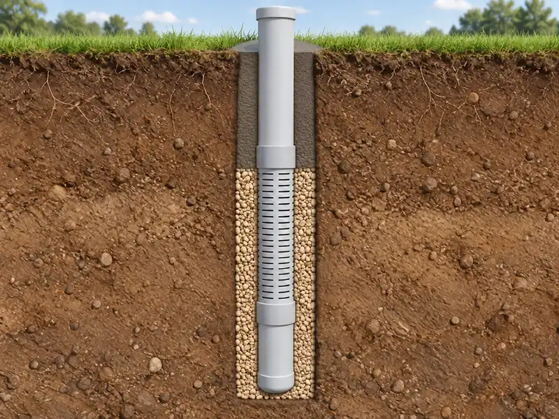
A well screen provides an entry region, while solid casing provides a continuous passage through other parts of the assembly. They work together but do not have interchangeable functions. The fact that water must enter somewhere does not mean it should enter along the entire pipe length.
The US EPA’s explanation of private well components distinguishes the casing that maintains the opening from screens that allow water to move into the well while limiting sediment entry. This functional distinction helps explain the use of both solid and screened pipe. Actual well design remains dependent on the site and intended application.
What Is Different About a Monitoring Interval?
For a monitoring well, the screened interval determines which part of the subsurface communicates with the inside of the well. Extending openings into another layer can change what the sample represents. A longer slotted section is therefore not automatically a better monitoring component.
The EPA’s monitoring well design guidance treats screen placement, casing and the surrounding construction as connected design decisions. Solid pipe alone does not isolate underground layers: the external sealing arrangement also matters. A drawing that shows only the pipe leaves those surrounding features unresolved, so it explains the component arrangement without defining the seals, ground conditions or construction details of an installed well.
What Role Can a Solid Bottom Section Serve?
Some assemblies include a short capped solid section below the screen, often described as a sump. It provides a region below the active openings where settled material may accumulate. Its inclusion and dimensions depend on the purpose of the assembly.
A sump is different from a blank end reserved for joining two manufactured lengths. Both may look like uncut pipe, but they occupy different positions and fulfil different functions. Naming the feature by its job prevents an apparently similar shape from being given the wrong meaning.
Scenario Three: Why Interrupt a Slot Pattern With Solid Bands?
A solid band leaves a continuous uncut region between groups of slots. It may be part of the intended structural layout or reserve space for a connection or handling feature. Its effect depends on its position, width and relationship to the remaining pattern.
Picture two pipes with equal total numbers of slots. One distributes them uniformly, while the other places them in several groups separated by uncut bands. Their total geometric opening area may be equal, yet the local arrangement of remaining material is different.
This is why opening percentage cannot describe the complete component. It says how much area has been removed under a stated calculation convention, but not where that removal occurs. The location of the remaining material belongs in the layout, not just in a single percentage.
A continuous band also does not restore every property of the original uncut pipe. Loads still pass through the slotted regions, and their geometry remains relevant. Claims about collapse resistance, tensile capacity or service depth require product-specific evidence.
| Uncut Feature | Main Purpose | Important Distinction |
| Blank connection end | Reserves space for joint geometry | Length follows the complete connection design |
| Intermediate solid band | Separates slot groups and preserves local continuity | Position matters as well as width |
| Solid casing section | Provides a passage outside the active screen interval | External seals remain part of the assembly design |
| Capped bottom sump | Provides space below the screen | Not simply an extra connection allowance |
How Does Reserving Solid Material Change the Available Screen Length?
It reduces the length available for active openings within a fixed overall component. Consider a hypothetical 3,000 mm pipe with 150 mm reserved at each end and a 100 mm solid band in the middle. The remaining 2,600 mm is available for the slotted groups, before any other design allowances.
Those dimensions are an arithmetic illustration, not a recommended product layout. They show why total length and active slotted length must be stated separately. Calling the whole 3,000 mm an active screen would misrepresent the component.
There are several possible responses when an application needs more entry area: a different slot arrangement, a longer active section or a different overall design. Removing connection material is not an automatic solution. Slot width must also continue serving its intended particle-retention function.
Our article on what determines slotted pipe open area explains the arithmetic in more detail. Here the key point is positional: the same quantity of openings can serve differently when placed in different zones.
How Does a Functional Layout Become a Manufacturing Pattern?
The layout becomes a sequence of cutting and non-cutting regions referenced to a defined end or datum. A recipe must account for the actual component length and the relationship between joints and active openings. Repeating a slot pitch alone does not describe where the complete pattern belongs.
For example, a repeating group may consist of a reserved end, several rows of slots, an uncut band and another slot group. The machine must reproduce the positions of both the slots and the deliberate gaps. Those gaps are specified product features, not missed cuts.
Yuyu’s DS250-SA pipe slotting machine is an equipment example for patterned pipe cutting. The precise end allowances and band layout still belong to the product drawing and the supplied machine’s capabilities. Our discussion of consistent slot patterns in PVC and PE pipes connects that drawing to repeatable positioning.
A well-defined slotted product gives every region a purpose. Openings provide the intended entry paths, and solid regions preserve space for the functions that require an uncut wall. Understanding both makes the layout more meaningful than a description based only on slot width or total opening percentage.