
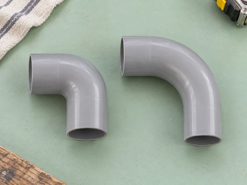
Bend radius changes how much room a PVC pipe needs to turn, where its straight sections end and how much curved centerline lies between them. At the same turning angle, a larger radius spreads the change in direction over a longer distance. A layout therefore needs a radius as well as an angle before the bend can be placed accurately.
This article uses ideal circular geometry to explain that space requirement. The examples are drawing calculations, not minimum bending radii, cutting instructions or operating settings. A manufactured bend also depends on the material, wall section and forming process.
Which Radius Belongs on the Drawing?
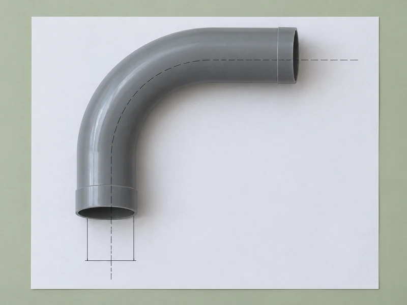
Use an explicitly identified reference, because the inside surface, centerline and outside surface follow different arcs. In the examples below, R means the centerline radius and D means the pipe outside diameter. That convention keeps the route of the pipe separate from the space occupied by its wall.
- Centerline radius: distance from the center of the circular bend to the pipe axis.
- Inside envelope radius: R minus half of D for the ideal undeformed section.
- Outside envelope radius: R plus half of D under the same assumption.
For an illustrative 50 mm outside diameter and 200 mm centerline radius, the inside and outside envelope radii are 175 mm and 225 mm. Calling all three dimensions simply the bend radius invites a 25 mm placement error. The drawing should identify which line the dimension reaches.
The circular-section assumption is useful for planning but does not predict the finished cross-section. Our explanation of ovality and wall thinning in bent plastic pipes describes why the real surface can depart from that ideal. Allowances for the actual product belong alongside the nominal geometry.
Why Does a Quarter-Turn Need More Than a Corner Point?
A circular 90-degree bend replaces the sharp intersection of two straight centerlines with a quarter-circle. Each tangent point sits one centerline radius away from that virtual intersection. The pipe begins turning before it reaches the imagined sharp corner and finishes after it has passed around it.
Sketch two perpendicular route lines meeting at a point. With R equal to 200 mm, mark 200 mm back along both lines and connect those marks with the appropriate circular arc. Those marks identify the transition between straight and curved centerline, rather than the two physical pipe ends.
A socket, straight tail or connection allowance can extend beyond either transition. Consequently, a 200 mm radius does not describe the complete overall length of a fabricated component. The bend geometry and its end features must be dimensioned separately.
What Changes When the Radius Doubles?
For the same 90-degree turn, changing R from 200 mm to 400 mm moves both tangent points farther from the virtual corner. The curved centerline also doubles in length. The direction of the outlet remains the same, but the space used to reach that direction changes substantially.
This creates a useful distinction between direction and position. Two bends can both turn through 90 degrees while their outlet locations differ when their inlet ends share a datum. Matching the angle alone will not make the components interchangeable in a constrained assembly.
How Can the Curved Length Be Calculated?
The centerline arc length follows the fraction of a complete circle used by the turn. For an angle expressed in degrees, multiply R by pi and by the angle, then divide by 180. The resulting length uses the same unit as R.
Centerline arc length = pi multiplied by R multiplied by turning angle in degrees, divided by 180.
OpenStax’s explanation of angles and arc length provides the underlying circle relationship. Applying that relationship to the pipe axis gives a geometric route length. It does not establish the neutral axis of a deforming wall or the exact length of stock consumed during forming.
| Illustrative Bend | Centerline Radius | Centerline Arc Length |
| 45-degree turn | 200 mm | Approximately 157.1 mm |
| 90-degree turn | 200 mm | Approximately 314.2 mm |
| 90-degree turn | 400 mm | Approximately 628.3 mm |
The first and second rows change angle while holding radius constant. The second and third change radius while holding angle constant. Reading them as separate comparisons makes clear which input caused the extra length.
Is Arc Length the Same as the Distance Between Tangent Points?
No: the straight chord joins the tangent points directly, while the arc follows the curved pipe axis. For a 90-degree bend with R equal to 200 mm, that chord is approximately 282.8 mm. It is shorter than the 314.2 mm centerline arc.
A tape pulled straight between the transitions measures a different quantity from a flexible line following the bend. Neither measurement is inherently wrong; they answer different questions. A drawing should avoid using one as a substitute for the other.
How Do Angles Other Than 90 Degrees Affect the Tangent Setback?
The setback from the intersection of the extended straight centerlines to either tangent point is R multiplied by the tangent of half the turning angle. Here the turning angle means the change in travel direction, not an ambiguously labelled interior corner angle. This relationship applies to an ideal circular bend with a turn greater than zero and less than 180 degrees.
For R equal to 200 mm and a 45-degree turn, the setback is approximately 82.8 mm. A 90-degree turn gives 200 mm because the tangent of 45 degrees equals one. Confusing a 45-degree direction change with a 135-degree interior angle would produce a completely different setback.
Near a 180-degree return, the extended route lines no longer offer a useful finite corner reference. A return bend is better described through its center spacing, radius and straight extensions. The dimensioning method should suit the shape rather than forcing every bend into the same corner calculation.
What Happens in a Constrained Layout?
Consider a hypothetical route around a cabinet where the inlet centerline and outlet direction are fixed. A broader bend begins turning earlier and may occupy space needed by another component. A tighter bend may fit the route drawing but still fall outside the forming capability of the selected pipe and tooling.
The practical solution is to treat available space and manufacturable geometry as two simultaneous constraints. Moving a connection, extending a straight run or changing the route can sometimes resolve the conflict. Simply reducing the radius on paper does not demonstrate that the corresponding pipe can be produced.
Pipe wall thickness also affects PVC bending, even when the desired footprint is unchanged. Two pipes with identical outside diameters can need different process arrangements. Their nominal centerline drawings do not reveal that difference.
Does a Larger Radius Solve Every Clearance Problem?
A larger radius can make the turn more gradual, but it uses more length along the adjacent routes. It may also move part of the pipe closer to a nearby obstacle. Clearance must be evaluated against the entire outer envelope, including sockets and connections.
For example, locating the centerline 20 mm from a flat surface cannot accommodate an undeformed 50 mm outside-diameter pipe. Half the diameter already requires 25 mm before adding any clearance allowance. This simple comparison catches a layout conflict that a radius dimension alone would miss.
How Does the Geometry Reach the Forming Process?
The production definition should connect the intended centerline shape to the actual pipe section and end arrangement. Yuyu’s pipe bending machine page describes forming with a mold or jig that establishes radius and angle. The supplied tooling and product specification determine which geometry can be reproduced.
A useful drawing sequence is to establish the route datum, identify tangent transitions, dimension the centerline radius and turning angle, and then add the physical envelope and end features. This separates the quantities that control fit from those that describe the process. It also gives different readers the same reference points.
The material being bent remains part of that definition. Geometry can be calculated consistently across materials, but forming behaviour cannot be inferred from geometry alone. The appropriate material and machine arrangement must support the required result.
Within the broader Yuyu pipe-processing equipment range, bending turns a route requirement into a shaped component. Radius explains how that direction change occupies space. Combining it with angle, tangent locations and pipe diameter makes the layout sufficiently clear to discuss the actual manufactured part.