
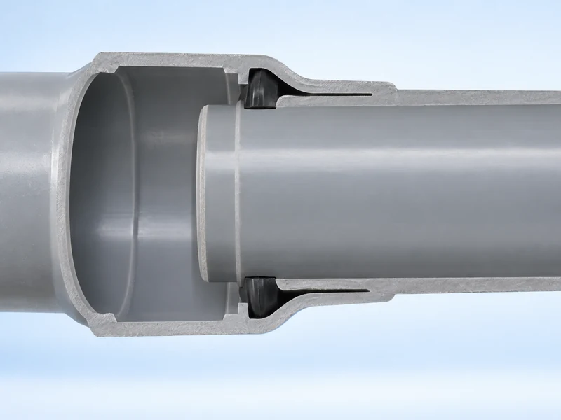
A gasketed PVC pipe joint needs its designed movement allowance because the pipe can change length as its temperature changes. The seal and the available axial space perform different functions: the gasket seals against the spigot, while the joint geometry provides the engagement and movement range intended for that product. An internal gap is therefore not automatically evidence of an incomplete joint.
The explanation here concerns conventional bell-and-spigot gasketed joints whose design permits limited axial movement. Restrained joints, special fittings and expansion devices can behave differently. Exact assembly positions and movement limits come from the pipe-system manufacturer.
What Is Happening Inside the Socket?
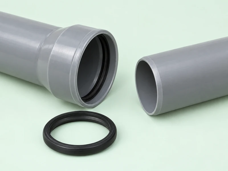
The enlarged bell receives the straight spigot end of the neighbouring pipe. A gasket held in the intended sealing region contacts the spigot surface. Farther inside, the end of the spigot may remain separated from a shoulder rather than bearing firmly against it.
Those locations should not be confused. The point where the gasket seals, the depth of spigot engagement and the remaining space beyond the spigot tip describe different aspects of the connection. A joint can have useful internal clearance while its sealing surfaces remain engaged.
Our guide to different socket types provides the wider shape context. Not every enlarged pipe end contains the same sealing arrangement. The presence of a socket alone does not identify its joint behaviour.
Why Does the Pipe Try to Change Length?
Temperature change produces dimensional change in the material. A useful first approximation relates free length change to initial length, temperature difference and the material’s linear expansion coefficient. The word free matters because supports and connected components may prevent the full movement from occurring.
OpenStax explains linear thermal expansion through that relationship. For pipe layout, it helps separate the movement the material would undergo freely from the movement that an installed system actually permits. The coefficient must be appropriate to the specific material and temperature range.
For the freely moving pipe in this model, first combine its starting length with the expansion coefficient, then apply the temperature difference to that product; the result represents the predicted increase or decrease along its axis.
For an arithmetic example only, suppose a coefficient of 0.06 mm per metre per degree Celsius, a 6 m length and a 20-degree Celsius temperature rise. The calculated free increase is 7.2 mm. This assumed coefficient is not a Yuyu product specification, and 7.2 mm is not a recommended joint gap.
Doubling the assumed length doubles the result if the other inputs stay fixed. Reversing the temperature change reverses the direction of movement in the simple model. These comparisons explain why the installation temperature and the later operating condition both matter.
How Does the Joint Respond Through a Temperature Cycle?
Think of the connection as a short overlap within a much longer system. The joint may accommodate some relative motion, but the distribution of that motion depends on the rest of the pipeline. One nearby gap cannot describe every displacement along the route.
At Assembly: Where Does the Movement Range Begin?
The manufacturer’s insertion reference establishes the intended initial position for that joint. It balances adequate engagement with the geometry needed for subsequent service. Deliberately pushing beyond the specified position changes that starting condition.
Uni-Bell’s technical brief on expansion gaps in gasketed PVC pipe explains that internal gaps are part of joint design for pressure and non-pressure products. It connects proper assembly with the pipe’s insertion reference. The brief supports understanding the gap’s purpose, rather than inventing a universal clearance dimension.
During Warming: Where Can the Extra Length Go?
If the installed arrangement allows movement toward a bell shoulder, warming can consume part of the available space. If movement is resisted, some of the dimensional tendency instead appears as loading in the system. Actual behaviour depends on restraint, friction and the connected geometry.
It is tempting to assign the entire calculated free expansion of a long route to one joint. That assumption may be inappropriate when several joints, bends, anchors and supports share the response. A system model needs to explain where movement is allowed and where it is resisted.
During Cooling: Why Must Engagement Remain Adequate?
Cooling tends to shorten an otherwise free pipe. Relative withdrawal at a joint must remain within the product’s permitted engagement range. Adding extra clearance without reference to that range can exchange one problem for another.
This is why more gap does not necessarily mean more useful flexibility. Both ends of the allowable travel matter. The connection must remain capable of performing its sealing and mechanical functions throughout the intended movement.
Which Quantities Are Often Mistaken for One Another?
Gap, engagement, angular deflection and restraint are related to joint performance, but they are not interchangeable. Describing them separately makes the limits of a connection easier to understand. It also avoids attributing capabilities to a gasket that belong to the complete joint.
- Axial clearance describes space available along the pipe axis within the relevant geometry.
- Engagement describes how far the spigot remains received by the socket.
- Angular deflection describes a permitted change in alignment at a joint.
- Axial restraint describes resistance to separation or longitudinal movement.
A joint that can seal while accommodating limited motion is not necessarily a restrained joint. Likewise, a stated angular allowance does not establish an unlimited sliding range. Each capability needs its own product-specific definition.
Yuyu’s rubber ring range includes rings for different pipe applications and assembly arrangements. That range illustrates why the gasket must match the intended joint design. A visually similar ring should not be treated as a substitute merely because it fits inside the bell.
How Do Two Installation Situations Differ?
Imagine two hypothetical lines made from the same nominal pipe. One lies in an environment with relatively small temperature changes; the other experiences a larger change between assembly and service. Their free expansion tendencies differ even before considering restraints.
Now suppose that the first line has little resistance to axial movement while the second is strongly constrained. The second line does not become dimensionally inactive just because it cannot slide freely. Its supports and connections must participate in the response to the temperature change.
These scenarios show why neither pipe material nor joint appearance is enough to predict system movement. Length, temperature history, route geometry and restraint all belong in the explanation. They do not establish a generic field adjustment that can be applied to every line.
Does the Air Temperature Fully Describe the Pipe Temperature?
Not necessarily: sunlight, surrounding soil and the fluid inside the pipe can produce different thermal conditions. The pipe may also take time to approach the temperature of its surroundings. A single ambient reading therefore does not always represent the full temperature change relevant to the component.
For a conceptual comparison, a shaded pipe and a sunlit pipe can start service at different material temperatures even on the same day. The movement calculation must use a defensible material-temperature range. Substituting a convenient weather value can hide the condition actually driving expansion.
What Does This Mean for Socket Manufacturing?
Manufacturing defines the receiving geometry that the finished joint relies on. The useful depth, sealing region and transition to the straight pipe must correspond to the intended product drawing. Enlarging the pipe mouth alone does not describe a complete functional socket.
Cooling during PVC pipe belling helps stabilise that formed geometry before handling. This manufacturing stage is distinct from thermal movement later in service. One concerns retaining the newly formed shape, while the other concerns dimensional response within an assembled pipeline.
The Yuyu belling machine range provides the equipment context for producing different pipe ends. Our separate explanation of PP socket blow forming shows another material and forming route. Its process details should not be transferred into a PVC joint specification.
The most useful way to view a gasketed joint is as a defined combination of sealing, engagement and permitted motion. Its internal space serves the design rather than representing unused material. Understanding those separate functions explains why the manufacturer’s assembly position matters throughout the temperature cycle.