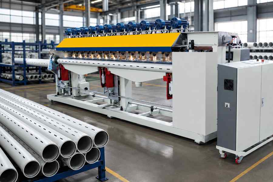
The production speed of an automatic pipe slotting machine is not determined by cutting speed alone. Plastic pipe size, slot pattern, feeding stability, tool condition, positioning time, chip removal, and automation level all affect the number of qualified pipes produced per hour.
How Is Pipe Slotting Speed Measured?
The production speed of a Pipe Slotting Machine describes how many qualified plastic pipes or slotted sections it completes within a defined period. It may be expressed as pipes per hour, slots per minute, or cycle time per pipe.
The most useful measurement depends on the product. Pipes with different lengths, diameters, and slot quantities should not be evaluated using one output figure.
Common speed terms include:
- Cycle time:Time required to load, position, slot, and discharge one plastic pipe.
- Slots per minute:Number of slots produced during continuous cutting.
- Pipes per hour:Number of completed pipes produced under normal operation.
- Qualified output:Finished pipes that meet slot size, spacing, and surface requirements.
- Downtime rate:Time lost to adjustment, tool replacement, cleaning, or material handling.
High movement speed is valuable only when slot accuracy and pipe quality remain stable. A slower cycle with fewer rejected pipes may deliver higher usable output over a full shift.
Main Factors Affecting Pipe Slotting Speed
| Main Factor | Effect on Production Speed |
| Pipe dimensions | Larger or longer pipes need more handling and support |
| Slot pattern | More slots and tighter spacing increase processing time |
| Cutting system | Tool type and spindle performance affect feed speed |
| Feeding and positioning | Unstable loading creates waiting and correction time |
| Chip removal | Poor collection causes cleaning stops |
| Automation and setup | Recipe control and fast changeover reduce delays |
These factors usually interact. For example, a long thin-wall plastic pipe may require slower feeding, stronger support, and more careful chip removal during the same cycle.
1. Plastic Pipe Diameter, Length, and Wall Thickness
Pipe Size Changes Handling Time
Larger-diameter plastic pipes are heavier and require stronger clamping and wider supporting structures. Longer pipes also take more time to feed, align, stabilize, and discharge.
The machine may complete the cutting movement quickly, but pipe transfer can become the longest part of the cycle. Buyers processing long drainage or filtration pipes should therefore inspect the complete loading-to-unloading sequence.
Wall Thickness Affects Cutting Load
Thicker pipe walls require the tool to remove more material from each slot. Cutting speed may need to be lowered to limit heat buildup, burr formation, vibration, and premature tool wear.
Thin-wall plastic pipes require less cutting depth but may deform under excessive clamping pressure. Additional support or gentler feeding can increase cycle time while protecting pipe roundness.
Pipe size should be assessed by considering both outside diameter and wall thickness. Pipes with identical outer dimensions may still need different cutting parameters because their wall structures are not the same.
2. Slot Quantity and Pattern Complexity
More Slots Extend Each Cycle
A pipe with a small number of widely spaced slots can be completed quickly. Production time rises when the machine must create multiple rows or hundreds of openings along the same pipe.
The pattern may include:
- Single-row slots
- Multiple longitudinal rows
- Staggered slots
- Spiral arrangements
- Alternating slot lengths
- Different spacing zones
Output claims should always state the tested slot pattern. A speed figure without slot quantity and spacing provides limited value for machine comparison.
Indexing Distance Affects Positioning
After each cutting action, the pipe or cutting head must move to the next position. Short slot spacing increases the number of stops, starts, and indexing movements.
Servo-controlled positioning can shorten these movements, but acceleration must remain suitable for the pipe. Excessive indexing speed may cause pipe slippage or cumulative spacing errors.
For multi-row patterns, pipe rotation also becomes part of the cycle. Rotation speed, locking time, and angular positioning accuracy can influence output as much as cutting speed.
3. Cutting Method and Tool Performance
Cutting Structure Sets the Speed Range
Automatic plastic pipe slotting machines may use saw blades, milling cutters, rotary tools, or punching structures. Each method offers a different combination of processing speed, slot geometry, edge finish, and suitable pipe wall thickness.
| Cutting Method | Speed Characteristic | Suitable Situation |
| Saw cutting | Fast for straight repeated slots | Standard drainage slot patterns |
| Milling | Controlled shape and smooth edges | Precise or wider slots |
| Rotary cutting | Supports continuous repeated processing | High-volume uniform patterns |
| Punching | Very short cutting action | Suitable pipe walls and supported shapes |
The method with the highest speed is not necessarily the most suitable option. The slot must meet the required width, length, spacing, and edge condition without damaging the plastic pipe.
Worn Tools Reduce Usable Output
A dull blade or cutter increases resistance and may require slower feed speed. It can also create burrs, melted edges, rough surfaces, or incomplete slots.
Operators may continue running the machine at its normal speed, but rejection rates and cleaning time will rise. Tool life monitoring is therefore part of production-speed control.
Buyers should ask how long a tool remains stable under their actual pipe material and slot pattern. Tool replacement time should also be included in the daily output calculation.
4. Feeding, Clamping, and Positioning
Automatic Feeding Must Remain Continuous
The cutting station cannot maintain high output when the next plastic pipe arrives late. Automatic loading, pipe separation, conveying, and length positioning should operate as one coordinated system.
Common feeding delays include:
- Pipes entering at an angle
- Two pipes feeding together
- Long pipes sagging between supports
- Pipe ends failing to reach the reference point
- Inconsistent gaps between incoming pipes
A high-speed slotting head cannot compensate for unstable material flow. In continuous production, reliable feeding often contributes more to hourly output than a small increase in cutting speed.
Clamping Must Be Fast and Stable
Clamps need enough force to prevent movement during slotting. However, excessive pressure can flatten thin-wall plastic pipes or leave contact marks.
Pneumatic or servo-controlled clamping can shorten closing and release time. The clamp structure should also adapt to different pipe diameters without requiring lengthy manual alignment.
Positioning accuracy affects whether the machine can run without repeated correction. When pipes slip or reference points vary, operators must slow the cycle or inspect more frequently.
5. Chip and Dust Removal
Waste Can Interrupt Cutting
Plastic chips may remain inside the slots, collect around the cutter, or enter the clamping area. As buildup increases, cutting resistance and positioning instability may also rise.
Poor chip removal can lead to:
- Blocked or incomplete slots
- Scratches on the pipe surface
- Higher cutting temperature
- Tool contamination
- Frequent manual cleaning
- Sensor detection errors
These interruptions reduce average production speed even when individual cutting cycles remain fast.
Collection Capacity Should Match Output
The extraction system should handle the waste volume produced at the intended machine speed. Small ducts, weak suction, or poorly positioned collection ports may work during short tests but fail during continuous production.
Plastic chip size also affects collection. Fine dust, long strips, and light curled chips do not move through the system in the same way.
A practical trial should run long enough to reveal buildup around the cutter and inside the pipe. A clean five-minute demonstration does not prove full-shift stability.
6. Automation and Control Response
Coordinated Motion Shortens Waiting
An automatic pipe slotting machine combines feeding, clamping, cutting, indexing, rotation, and discharge. Production speed improves when these actions overlap safely rather than waiting for every previous movement to finish completely.
Servo systems can coordinate:
- Pipe feeding distance
- Slot spacing
- Cutting-head travel
- Pipe rotation angle
- Tool entry and return
- Final discharge
The control system should optimize non-cutting movement without weakening accuracy. Rapid travel is most useful between slot positions, while cutting feed should remain matched to the plastic pipe.
Recipe Storage Reduces Setup Time
Different pipe sizes and slot patterns require different parameters. Manual entry during every changeover increases setup time and creates a greater risk of incorrect values.
A stored recipe may include:
- Pipe diameter and length
- Slot quantity and spacing
- Slot depth and width
- Number of rows
- Rotation angle
- Cutting feed speed
- Clamp pressure
- Chip-removal settings
Recipe recall is particularly valuable for factories producing small batches of several pipe specifications. It may not change the fastest cycle, but it can significantly increase daily output.
How to Calculate Real Production Speed
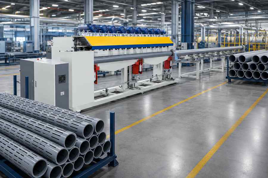
Rated production speed is often based on stable operation with one pipe specification. Actual daily output must also include loading, tool replacement, changeover, cleaning, inspection, and short production stops.
A practical evaluation should record:
| Production Item | What to Measure |
| Cutting cycle | Time from clamping to completed slots |
| Handling cycle | Loading, positioning, and discharge time |
| Changeover | Time required to switch pipe specifications |
| Maintenance stops | Tool replacement and chip cleaning |
| Qualified output | Accepted pipes after inspection |
The most useful figure is qualified pipes per shift. This measurement shows whether higher machine speed genuinely improves production or simply creates more defects and interruptions.
Warning Signs Behind an Unrealistic Speed Claim
A production-speed figure may be misleading when it excludes loading, discharge, cleaning, or tool replacement. It may also be based on a short pipe with only a few simple slots.
Other warning signs include:
- No pipe diameter or wall thickness stated
- No slot quantity included
- Speed measured without automatic feeding
- Output based on one short test
- No finished-slot inspection
- No continuous chip-removal test
- No changeover time provided
A useful machine specification should describe both speed and test conditions. Output figures become meaningful only when they match the buyer’s actual plastic pipe products.