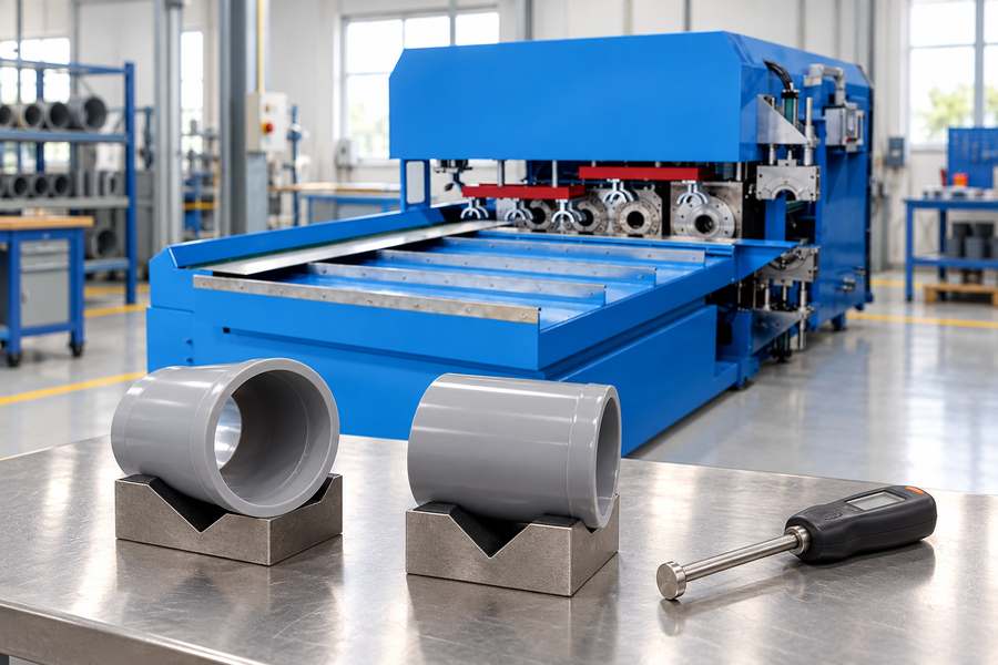
Both inner and outer pipe surfaces matter when evaluating belling-machine heating, even if heat enters from one side. Buyers should check the forming zone along the pipe and around its circumference.
Heater settings cannot establish pipe temperature alone. A purchase specification should define measurement locations, instrument limitations, transfer timing, and acceptance evidence while confirming the supplied heating configuration.
How Does Internal vs External Heating Affect Pipe Temperature?
Heating direction determines which pipe surface receives thermal energy first and how heat travels through the wall. External and internal heating therefore require different measurement priorities.
Matching the two surface readings is not, by itself, evidence that the pipe is ready to form. The aim is to establish a suitable temperature distribution throughout the material that will undergo socket forming.
External Heating and Outer-Surface Temperature
External heating introduces energy through the outside of the pipe. The outer surface generally responds before the inner surface, although actual temperature differences depend on the equipment and material.
Contact heating transfers energy through the interface between the heating tool and pipe. Contact quality, positioning, and local surface conditions can influence the resulting temperature distribution.
Oven heating transfers energy through a different arrangement. Pipe rotation may improve circumferential exposure, but uniform rotation does not independently establish uniform pipe temperature.
For external heating, buyers should examine both the directly heated outer surface and the inner wall. An acceptable outer reading cannot establish that sufficient heat has penetrated the material.
Wall thickness and heating duration are particularly important. A thicker wall may retain a substantial temperature difference between its surfaces when heating ends.
Internal Heating and Inner-Surface Temperature
Internal heating delivers thermal energy from the pipe bore toward the outer wall. Depending on the heating arrangement, the inner surface may warm more rapidly.
This reverses the principal direction of heat transfer compared with external heating. Buyers should therefore establish how the outer wall responds before the pipe enters forming.
Internal heating does not necessarily mean that heat reaches every circumferential position equally. The actual heater arrangement, exposure conditions, and pipe positioning determine the distribution.
Where equipment also uses external heating components, buyers should establish how the heating functions operate together. A product description alone may not reveal their operating sequence.
Verified Heating Configurations from Yuyu Machinery
Yuyu Machinery lists aluminum-block contact heating OR oven heating with rotary pipe for its DS110S multi-pipe belling machine. These are published heating alternatives, not proof that both operate simultaneously.
For its DS160PP-NII internally heated blow-type belling machine, Yuyu Machinery lists aluminum-block contact heating, a stainless steel heating tube, internal heating, blow-type forming, and water cooling.
Those descriptions establish listed product features, but they do not define the exact internal heater geometry, pipe contact locations, or installed temperature measurement arrangement.
Buyers should request configuration drawings and identify the heating method supplied. The following measurement recommendations are general engineering checks, not confirmed features of either machine.
Which Inner and Outer Pipe Surfaces Need Temperature Checks?
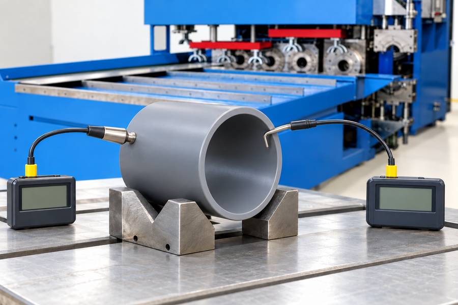
Temperature verification should distinguish the surface receiving heat from the opposite surface. Both contribute information about the thermal condition of the pipe wall before deformation.
Measurements should focus on the material entering the forming operation rather than accessible locations that may not represent the intended socket region.
The Surface Receiving Direct Heat
The directly heated surface provides the clearest indication of local heat delivery. For external heating, this is generally the outer wall; for internal heating, it is the inner wall.
However, measurements must correspond to actual heating coverage. A temperature reading outside the critical forming region may appear acceptable while another section remains inadequately heated.
Contact heating also requires attention to local differences. Uneven contact, tool alignment, or surface variation can produce temperature differences that a controller sensor does not reveal.
For oven heating, surface readings should be associated with the pipe position and heating sequence. Measurements taken after rotation stops may not represent all circumferential positions.
The Opposite Pipe Surface
The opposite surface indicates how effectively heat has traveled through the pipe wall. Its temperature is relevant even when that surface does not directly contact a heater.
For externally heated pipes, buyers should investigate the inner-wall condition. For internally heated pipes, the corresponding concern is the outer-wall temperature.
These measurements become especially important when wall thickness or material characteristics change. Identical heater settings may produce different through-wall distributions under different processing conditions.
Direct access is not always practical. When the opposite surface cannot be measured, buyers should agree on an indirect assessment supported by representative forming trials.
Temperature Differences Across the Pipe Wall
A temperature difference between the two surfaces is expected during transient heating. The engineering question is whether the resulting distribution supports the intended forming operation.
Material near the hotter surface may deform differently from material deeper in the wall. Such differences can influence socket geometry and surface condition.
Surface measurements cannot fully reconstruct the temperature profile throughout the wall. Additional thermal analysis or representative trials may be necessary when through-wall behavior is critical.
Acceptance criteria should reflect the pipe material, wall thickness, and forming process. No universal allowable temperature difference applies to every belling-machine application.
Where Should Temperature Be Measured Along and Around the Pipe End?
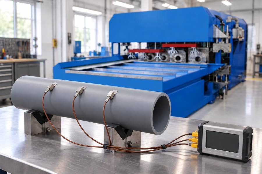
A single temperature measurement is insufficient for evaluating an entire socket-forming region. Temperature mapping should cover both the pipe’s axial direction and its circumference.
The measurement plan should reference the actual socket geometry, including regions that must deform and transitions where unwanted deformation needs to be avoided.
Axial Temperature Mapping Across the Forming Zone
Axial mapping examines how temperature changes along the pipe length. Measurement positions should begin near the pipe end and extend through the intended forming region.
The transition between heated and relatively unheated material deserves attention. An abrupt or misplaced temperature change may affect where deformation occurs during forming.
Buyers should identify each measurement position using a consistent reference, such as its distance from the pipe end. Positions must correspond to agreed socket dimensions.
For different pipe diameters or socket designs, measurement positions may need adjustment. Reusing an unchanged map without considering forming geometry can produce misleading comparisons.
Circumferential Temperature Mapping
Circumferential mapping compares temperatures at multiple angular positions around the pipe. It helps identify variations that a single accessible measurement location would otherwise conceal.
In contact heating, uneven engagement or pipe positioning may affect the temperature pattern. In rotary heating, exposure and actual rotational behavior require consideration.
Readings should be taken at comparable stages of the heating cycle. Otherwise, differences in measurement timing may be mistaken for genuine circumferential temperature variation.
Any reported nonuniformity should also be evaluated against instrument limitations. Reflections, viewing angles, and probe placement can introduce differences unrelated to actual heating.
Building a Repeatable Surface Temperature Map
A useful map identifies the pipe surface, axial position, angular position, and measurement timing. This information allows the buyer to compare trials under equivalent conditions.
Inner- and outer-surface readings should be recorded separately. A measured surface temperature should never be presented as an established average temperature through the wall.
Table 1 identifies the main measurement areas and their purchasing implications.
| Measurement area | Main engineering concern | Buyer verification requirement |
| Directly heated surface | Local heat delivery and uniformity | Measure relevant positions on the actual pipe surface |
| Opposite surface | Heat penetration through the wall | Measure directly where practical or agree on an indirect assessment |
| Axial forming region | Temperature variation along socket length | Map positions across the forming region |
| Circumferential positions | Uneven heating around the pipe | Compare repeatable angular positions |
| Heating-zone transitions | Temperature differences near forming boundaries | Include relevant boundary positions |
The final measurement map should be agreed upon before acceptance testing. Its locations and limits must reflect the actual pipe application, not arbitrary universal values.
How Can Buyers Distinguish Heater Temperature from Actual Pipe Temperature?
A heater controller indicates conditions at its associated control point. It does not necessarily measure the pipe surface, much less the temperature throughout the wall.
Buyers should establish what every displayed temperature represents before using controller readings as evidence of forming readiness.
Heater Setpoints, Sensor Readings, and Pipe Temperatures
A setpoint defines the controller’s target for its controlled variable. The actual sensor may measure a heating element, aluminum block, or oven environment.
Heat-transfer resistance and thermal response delays can create substantial differences between those readings and the pipe surface, depending on the operating conditions.
Even a stable heater reading does not establish uniform pipe heating. The pipe continues absorbing and redistributing energy according to its material properties and exposure.
Equipment documentation should identify sensor locations, controlled variables, and available readings. Independent surface measurements may be necessary to establish the relationship with pipe temperature.
Suitable Measurement Methods and Their Limitations
Measurement methods differ in accessibility, response, and uncertainty. Buyers should select them according to the actual surface being checked rather than instrument availability alone.
Infrared measurements are useful without direct contact, but pipe emissivity, viewing angle, reflections, and measurement spot size can affect the indicated temperature.
Thermal imaging can reveal surface patterns across a wider region. Accurate absolute measurements still depend on appropriate instrument settings, calibration, and interpretation.
Contact probes measure local accessible surfaces. Their readings depend on contact quality, sensor response, and the extent to which the measurement disturbs the surface.
Table 2 compares available measurement approaches without implying that either Yuyu Machinery model includes all these instruments.
| Measurement method | Typical purpose | Important limitation |
| Infrared thermometer | Noncontact surface spot measurements | Emissivity, reflections, and spot-size effects |
| Thermal imaging | Mapping surface temperature variation | Calibration and interpretation of thermal images |
| Contact temperature probe | Checking accessible local surface temperatures | Contact quality and sensor response time |
| Installed machine sensor | Monitoring its designated control or measurement point | May not directly measure pipe temperature |
Measurement access is another consideration. Inner-wall readings may be difficult when heating tools obstruct the bore, while enclosed heaters can restrict external observation.
Where instruments cannot directly measure a critical surface, the acceptance plan should state that limitation and describe the agreed method for evaluating its thermal condition.
When Should Pipe Temperatures Be Checked During the Heating and Forming Cycle?
Temperature changes throughout the belling cycle. A measurement has limited value unless its timing is identified relative to heating completion and the start of forming.
The purchasing specification should therefore define measurement events, not merely temperature locations or nominal heating duration.
During Heating and at Heating Completion
Measurements during heating can help reveal how the pipe responds over time. However, heating tools, enclosures, and pipe movement may restrict direct surface access.
The machine’s displayed heater temperature should be recorded separately from any independently measured pipe temperature. These readings represent different physical quantities.
At heating completion, buyers should establish whether the pipe surfaces have reached the application-specific conditions required for the next process stage.
A recorded value should include its measurement time. Without that reference, comparison between different cycles may reflect timing differences rather than heating performance.
During Transfer from Heating to Forming
After heating ends, exposed pipe surfaces may begin cooling while heat continues redistributing within the wall. Consequently, surface temperatures can change before deformation begins.
The transfer interval includes the relevant movement and positioning between heating and forming. Its actual duration should be established for the supplied machine configuration.
Measurements taken immediately after heating may differ from those taken closer to forming. Neither should be interpreted without identifying the corresponding cycle event.
Buyers should require a repeatable timing reference so that representative trials can be compared without confusing thermal changes with measurement inconsistencies.
At Forming Readiness
The most relevant temperature condition is the material’s state when forming begins. Earlier measurements must be interpreted alongside any intervening cooling or redistribution.
Forming-tool contact can subsequently alter local thermal conditions. Measurements after contact therefore do not necessarily represent the condition immediately before deformation.
Similarly, post-cooling temperatures cannot independently establish preforming temperatures. They describe a later process stage with different thermal conditions.
Temperature records should be correlated with socket dimensions and surface inspection. Suitable temperatures alone cannot establish acceptable forming when tooling or process conditions are unsuitable.
What Temperature Verification Requirements Should Buyers Include in a Belling Machine Specification?
A purchasing specification should translate temperature-checking principles into measurable requirements. It must distinguish the machine’s published features from verification activities requested by the buyer.
The scope should identify who supplies measurements, how results will be evaluated, and which records are required for acceptance.
Define Heating Configuration and Measurement Requirements
The supplier should first confirm the actual heating arrangement, including relevant components and heating sequence. Published product descriptions should not substitute for configuration-specific documentation.
Buyers should also identify representative production requirements. Pipe material, diameter, wall thickness, and socket geometry influence the appropriate temperature-checking approach.
The request should address four specific items:
- Heating configuration: Confirm the supplied heating method, installed sensor functions, and relevant measurement access.
- Measurement locations: Define inner- and outer-surface positions along the pipe and around its circumference.
- Measurement methods: Identify suitable instruments, access limitations, and any agreed indirect assessments.
- Cycle references: Establish when measurements occur relative to heating completion, transfer, and forming.
These are recommended purchasing requirements rather than confirmed standard functions of the DS110S or DS160PP-NII. Any requested additional instrumentation should be included explicitly.
Agree on Pass Criteria for the Pipe Being Tested
Choose the acceptable temperature range for the pipe compound, wall section, and socket profile in the trial. A universal heating setting is unsuitable across different pipe constructions and forming processes.
Acceptance criteria should distinguish heater control performance from measured pipe-surface conditions. Agreement on one does not automatically establish compliance with the other.
Measurement uncertainty also matters. Small differences between readings may lack engineering significance when instrument accuracy, placement variation, or response limitations are considered.
The buyer and supplier should agree on evaluation methods before testing. Criteria must specify the temperatures or distributions being assessed and their associated process conditions.
Verify Performance Under Representative Production Conditions
Acceptance trials should use pipe materials, dimensions, and wall thicknesses representing the intended production scope. This helps establish whether the temperature-checking method remains meaningful.
The trials should record actual heating conditions rather than relying solely on nominal settings. Pipe-surface measurements should follow the agreed map and timing references.
Formed sockets should then be inspected against their dimensional and surface requirements. Temperature readings are supporting evidence, not a replacement for physical product inspection.
When irregularities occur, investigation should consider heating distribution alongside tooling, forming conditions, alignment, and cooling. Assigning every defect to temperature risks overlooking other causes.
Required Temperature Verification Records
The final verification package should connect each measured temperature with its location, timing, equipment configuration, and corresponding production trial.
Records should also identify which observations are direct measurements and which depend on estimates, thermal analysis, or other agreed indirect assessment methods.
A practical documentation package should contain:
- Configuration record: Supplied heating arrangement, relevant components, and installed sensor functions.
- Temperature map: Defined pipe surfaces, axial positions, angular positions, and recorded readings.
- Measurement record: Instruments, methods, uncertainty considerations, and documented measurement-access limitations.
- Cycle timing record: Heating completion, measurement events, transfer interval, and forming-start references.
- Acceptance record: Agreed criteria, inspected socket results, deviations, and required corrective actions.
These deliverables give buyers a traceable basis for evaluating heating performance. Final acceptance should follow the agreed pipe requirements and verified results, without assuming undocumented equipment capabilities.