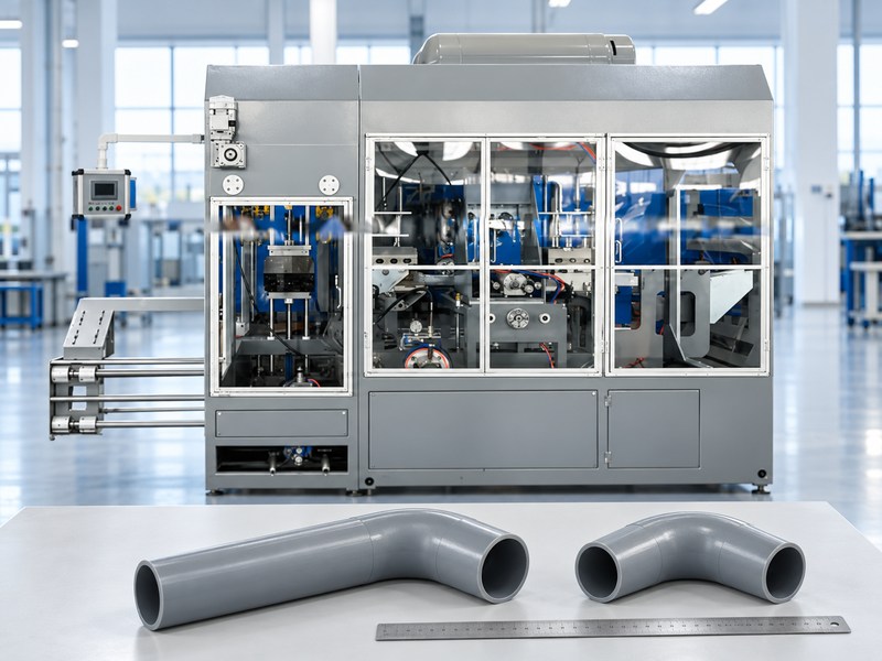
Specify each straight end from its bend tangent point to the finished end face. Choose the length to accommodate the intended connection and assembly clearance, then confirm that the machine can grip, support, and form the part with the agreed heating and trimming sequence.
Dimension the two ends separately. They may serve different joints or require different tooling access, even when the bend itself is symmetrical.
Establish Exactly Where Each Straight End Begins
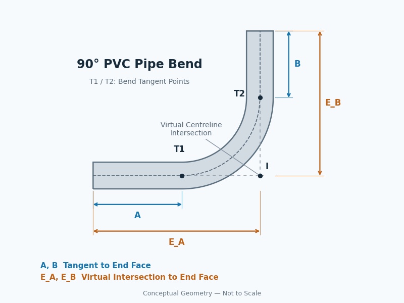
A straight end length needs two identifiable references: the tangent point where the curved centreline meets the straight axis, and the final cut face. An overall leg dimension measured from a virtual corner is a different quantity.
Define these items on the finished-part drawing:
| Drawing Item | Required Definition |
| Bend angle | Change in direction between the inlet and outlet axes |
| Bend radius | Centreline radius, explicitly identified |
| End A | Tangent-to-face length and end connection |
| End B | Tangent-to-face length and end connection |
| End features | Socket, chamfer, insertion mark, or other specified preparation |
| Acceptance condition | When and how the cooled part is measured |
If a socket occupies part of a straight leg, show its length separately. The tangent-to-face dimension then describes the complete end region; it does not mean the entire region has a constant outside diameter.
For custom PVC pipe bending equipment, submit this drawing before requesting a minimum end length. A machine supplier can assess defined geometry more reliably than a photograph with an approximate overall size.
Set the Connection Requirement at Each End
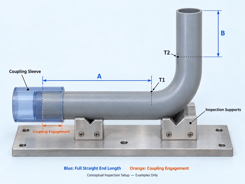
Begin with the mating component. The usable straight region must allow the intended joint to engage without the bend transition entering a sealing, bonding, or gripping area that requires a straight cylindrical surface.
Prepare a separate connection record for each end:
- Joint type and mating-component drawing.
- Required insertion or engagement length.
- Permitted pipe-end diameter and roundness.
- Chamfer, surface condition, and preparation requirements.
- Clearance needed for assembly tools or installation movement.
- Position of any insertion mark or end stop.
| End Arrangement | Straight-End Question to Resolve |
| Plain spigot entering a coupling | Can the full required engagement remain on acceptable straight pipe? |
| Solvent-cement socket connection | Does the mating geometry and preparation follow the specified joint system? |
| Gasketed connection | Does the seal contact the intended straight surface throughout assembly? |
| Socket formed on the bend | Is sufficient end stock available for socket forming and final engagement? |
| Mechanical coupling | Can its seal and gripping elements occupy their approved contact zones? |
Do not assign one insertion depth to every pipe diameter or connection type. Use the selected joint documentation, and confirm whether assembly clearance is additional to the engagement length or already included in another dimension.
When reviewing custom bending configurations, include the actual coupling or socket details. A bend that fits the route can still leave too little usable straight surface for the joint.
Confirm the Machine Contact Zones Before Fixing the Length
Finished-part geometry and manufacturing access must agree. Depending on the forming arrangement, the machine may need a straight region for clamping, locating, internal tooling, pressure containment, or transfer support.
Ask the supplier to mark those contacts on the proposed part and blank drawings.
Separate Permanent Length From Temporary Process Stock
| Process Requirement | What to Confirm |
| Clamp contact | Required contact length and distance from the heated transition |
| Axial location | Which face or mark sets the blank position |
| Internal tool access | Entry path, engagement, and withdrawal clearance |
| Pressure seal, if used | Required sealing surface and its condition |
| Support and transfer | Contact locations during heating, forming, cooling, and discharge |
| Sacrificial stock | Whether extra gripping length is removed after forming |
Yuyu’s PVC pipe bending machine page includes the DS63-BM, with infrared heating, inner-mould air forming, outer-mould shaping, and water cooling. Its listed blank-length range is not a minimum straight-end specification for every bend.
Confirm the end requirement against the supplied tooling. If a short finished end needs temporary gripping stock, establish how that stock is located and trimmed without damaging the accepted part.
Translate Installation Dimensions into Tangent-to-Face Lengths
Installation drawings often locate end faces from the intersection of extended straight centrelines. Convert those dimensions before discussing straight ends with the tooling supplier.
For an ideal circular bend with turning angle θ between 0 and 180 degrees:
- Tangent setback: T = R × tan(θ / 2).
- Straight end A: A = E_A − T.
- Straight end B: B = E_B − T.
Here, R is the centreline radius. E_A and E_B are distances measured along each extended straight axis from the virtual intersection to its end face, on the corresponding tangent side.
Check a Simple Drawing Example
| Quantity | Illustrative Value |
| Turning angle | 90 degrees |
| Centreline radius R | 150 mm |
| Tangent setback T | 150 mm |
| Corner-to-face dimension E_A | 250 mm |
| Corner-to-face dimension E_B | 290 mm |
| Resulting straight end A | 100 mm |
| Resulting straight end B | 140 mm |
These values describe geometry only. They do not establish acceptable connection lengths, minimum tooling access, or a production cutting recipe.
If the calculated end is too short, review the route, connection position, radius, or tooling arrangement together. For further geometric context, see how bend radius changes a PVC bend’s footprint.
Keep the Heating Boundary Separate From the Geometric Tangent
The tangent point is a drawing reference. The practical heating boundary depends on the forming process and need not stop exactly at that point.
A short thermal transition may extend toward the nominal straight leg. Determine whether that region still meets the joint’s diameter, roundness, straightness, and surface requirements after cooling.
Review the following during trials:
- Mark the proposed tangent and connection engagement regions on the blank or trial documentation.
- Record the heating arrangement and exposed length.
- Check the cooled straight legs for distortion near the transition.
- Compare the mating component’s full contact area with the accepted straight surface.
- Adjust the heating arrangement or end geometry if the functional regions conflict.
Do not move the drawing tangent merely to conceal a distorted end. Revise the manufacturing arrangement or formally change the approved geometry.
Separate the Finished Length From the Blank and Trimming Allowance
An unformed blank may contain material that will not remain in the delivered bend. Keep that allowance on the process drawing rather than adding it silently to the finished-part dimension.
For an ideal circular centreline, the geometric path is:
Finished centreline path = A + B + πRθ / 180
This provides a drawing check, not an exact stock-consumption prediction. Establish the production blank length through trials, accounting for forming behaviour and subsequent operations.
| Length Category | Where to Record It |
| Finished straight ends A and B | Customer-approved part drawing |
| Geometric curved path | Design calculation or drawing reference |
| Gripping and locating allowance | Process drawing and tooling review |
| End trimming allowance | Cutting and finishing instruction |
| Socket-forming allowance, if needed | Approved sequence for the actual joint |
Decide whether sockets are formed before or after bending, and when final trimming occurs. Earlier end preparation can affect tooling access; later preparation needs sufficient remaining stock and a suitable locating method.
Inspect the final end faces after all specified operations. A length approved immediately after bending may change when the part is trimmed or socketed.
Specify Tolerances That Protect Assembly
Straight-end length alone does not locate an outlet. Bend angle, radius, end-axis direction, and face position also affect assembly.
Choose a consistent datum scheme and identify the dimensions that control interchangeability.
Include the Adjacent End Conditions
- Length tolerance for each end.
- Straightness of the required engagement region.
- End-face squareness to the corresponding straight axis.
- Diameter and roundness where the joint contacts the pipe.
- Finished bend angle and relevant positional dimensions.
- Permitted clamp marks or surface damage.
Avoid independently tightening every dimension without checking their geometric relationships. Where overall endpoint position is critical, identify it as a functional requirement and agree on a suitable inspection fixture.
Use the approved product specification to set numerical limits. A tolerance achievable on one diameter and wall section should not automatically be copied to another.
Inspect the Cooled Bend Against Defined References
Use the conditioning requirements in the agreed quality procedure before final acceptance. Record the part’s support arrangement so the inspection fixture does not force it into the desired shape.
| Inspection Step | Practical Method |
| Confirm identity | Check pipe material, size, wall specification, and drawing revision |
| Establish the datum | Locate the agreed straight leg or end face without distortion |
| Check tangent references | Use the approved nominal profile or fixture method |
| Measure both end lengths | Measure along the respective straight axes |
| Check engagement regions | Inspect roundness, straightness, and surface condition |
| Verify assembly | Use the approved mating component or defined gauge |
| Record the result | Identify the sample, conditioning, tooling, and measurements |
The tangent can be difficult to locate visually on a gradual transition. Agree on a measurement method during sample approval rather than allowing each inspector to choose where the curve appears to start.
Put the Approved End Lengths Into the Purchase Specification
Before ordering tooling or equipment, assemble one consistent technical package:
- Finished-part drawing with A and B, radius, angle, datums, and tolerances.
- Connection drawings and required usable engagement regions.
- Pipe material, actual diameter, wall specification, and incoming variation.
- Machine contact zones and any temporary gripping stock.
- Heating, cooling, socketing, and trimming sequence.
- Trial sample identification and inspection results.
- Product-to-tooling matrix for all requested bend variants.
Where a proposed short end remains uncertain, request a representative forming and assembly trial. Approve the finished geometry and process allowance together, so the end that fits the installation is also the end the machine can repeatedly produce.