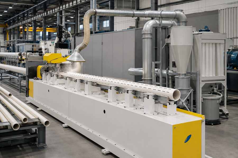
Plastic pipe slotting produces more than finished openings. Cutting tools also create fine dust, short chips, curled strips, and loose particles that can remain inside the pipe or collect around the machine.
An effective collection system keeps the cutting area cleaner, reduces manual cleaning, and helps the slotting line maintain stable output. The best solution should match the plastic material, slot pattern, pipe size, and actual waste volume.
What Waste Does Plastic Pipe Slotting Produce?
The waste generated by a pipe slotting machine depends on the plastic material, wall thickness, cutter type, feed speed, and slot dimensions. Fine dust and long curled chips require different airflow and separation methods.
| Waste Type | Typical Cause | Collection Need |
| Fine dust | High-speed cutting or dry milling | Strong local extraction and fine filtration |
| Short chips | Sawing or rotary cutting | Wide intake and chip separator |
| Curled strips | Deep or continuous slotting | Larger ducts and anti-blocking design |
| Internal residue | Chips falling into the pipe | Internal suction or pipe cleaning |
| Warm sticky particles | Excessive cutting heat | Better cutting control and easy-clean ducts |
Mixed waste is common when one machine processes several plastic pipe specifications. The collection system should handle the most difficult waste type rather than only the easiest production sample.
Main Dust and Chip Collection Solutions
No single collection method fits every plastic pipe slotting line. Stable systems usually combine local capture, duct transport, separation, filtration, and waste discharge.
Local Extraction at the Cutter
A local extraction hood captures dust and chips close to the point where the cutter enters the plastic pipe. Shorter capture distance usually improves removal efficiency and reduces the airflow needed across the wider machine enclosure.
The hood should surround the cutting area without blocking tool travel or pipe rotation. Adjustable designs are useful when the line processes several pipe diameters or slot depths.
Important hood features include:
- Close position to the cutter
- Opening matched to chip direction
- Adjustable height or angle
- Easy access for tool replacement
- Smooth internal surfaces
- Minimal interference with sensors
A large hood placed far from the cutting point may look effective but collect waste poorly. Concentrated capture at the source is usually more practical than trying to clean the complete machine chamber with one distant outlet.
Internal Pipe Suction
Some chips fall through the slot and remain inside the plastic pipe. External extraction may clean the cutter area while leaving internal residue that later blocks slots or spills during handling.
Internal suction can be applied through the pipe end or through a movable extraction nozzle. This method is especially useful for long plastic pipes, dense slot patterns, and applications requiring clean internal flow paths.
Internal cleaning may use:
- End-mounted suction nozzles
- Movable vacuum tubes
- Air-assisted chip transport
- Pipe rotation during suction
- Timed cleaning after slotting
The suction point should remain close enough to move chips through the pipe. Very long pipes may require extraction from both ends or a cleaning stage that travels along the pipe length.
Centralized Duct and Separator System
A centralized system connects one or more slotting stations to a common fan, duct network, and separation unit. It can simplify waste handling when several cutters operate within the same production line.
The first separation stage should remove larger chips before air reaches the fine filter. Cyclone separators, drop-out boxes, or chip chambers can reduce filter loading and extend cleaning intervals.
| System Component | Main Function |
| Extraction hood | Captures waste at the cutter |
| Main duct | Carries dust and chips away |
| Chip separator | Removes larger particles |
| Fine filter | Captures smaller airborne dust |
| Fan or blower | Maintains required airflow |
| Collection bin | Stores separated waste |
Duct layout has a direct effect on performance. Long horizontal runs, sharp bends, small pipework, and unnecessary branches can reduce transport speed and create chip buildup.
Secondary Filtration and Waste Storage
Fine dust may pass through the first chip separator and require a secondary filter. Cartridge filters, bag filters, or another suitable filtration stage can be selected according to particle size and expected dust load.
Filter area should be large enough for continuous production. An undersized filter may perform well when clean but lose suction quickly as dust accumulates.
Waste storage also affects uptime. Collection bins should be large enough for the planned shift and simple to empty without spreading dust back into the working area.
Useful options include:
- Differential-pressure monitoring
- Automatic filter cleaning
- Full-bin sensors
- Quick-release waste containers
- Sealed discharge bags
- Transparent inspection windows
A collection unit should remain serviceable without stopping the complete slotting line for long periods. Filter access, bin removal, and duct cleaning should be considered during machine layout.
How to Select the Right Collection System
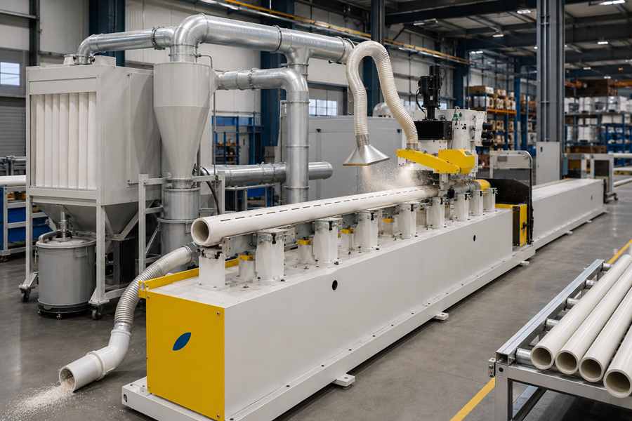
Collection capacity should be based on actual waste generation rather than motor power alone. The number of cutting heads, slot quantity, pipe wall thickness, and cutter speed all change the required airflow.
Match the System to the Plastic Pipe
Larger pipes may produce more chips per slot, while thick-wall pipes create a greater cutting volume. Long pipes also make internal chip removal more difficult.
The supplier should review:
- Plastic pipe material
- Outside diameter
- Wall thickness
- Pipe length
- Slot width and depth
- Number of slots
- Number of cutting heads
- Expected hourly output
Different plastic formulations can produce different waste shapes. One material may create light dust, while another forms longer strips that are more likely to block small ducts.
Size Airflow for Simultaneous Cutting
A system serving several cutting heads should be sized for the number of heads operating at the same time. Adding each hood’s airflow without checking duct balance can leave the farthest station with weak suction.
Dampers or independent branches can help balance the network. However, excessive adjustment should not be required whenever one cutting head starts or stops.
The fan should provide stable airflow under normal filter loading. Performance measured only with a clean filter may overstate continuous production capacity.
Prevent Duct Blockage
Plastic chips are light but may be long, curled, or statically charged. They can collect at elbows, reducers, flexible hose sections, and low-airflow branches.
A practical duct design should include:
- Smooth internal walls
- Gradual bends
- Limited horizontal sections
- Suitable transport velocity
- Accessible cleaning points
- Minimal diameter changes
Flexible hoses are useful near moving cutting heads, but long flexible runs create more resistance. Rigid ducting is generally more suitable for the main transport route.
Collection System Performance and Purchase Evaluation
Buyers should provide actual plastic pipes and representative slot drawings during the equipment trial. The test should use the intended cutter type, slot quantity, pipe length, and production speed.
The supplier should run the line continuously long enough to reveal dust buildup, duct blockage, or declining suction. A short demonstration cannot show how the filter and waste bin perform across a normal shift.
Important purchasing checks include:
- Dust remaining around the cutter
- Chips left inside the pipe
- Slot cleanliness after processing
- Suction stability during continuous cutting
- Filter-cleaning frequency
- Waste-bin capacity
- Access for duct and hood cleaning
- Noise and energy use
- Changeover between pipe sizes
Buyers should also inspect pipes after transfer and discharge. Waste that appears controlled at the cutting station may still fall from the pipe later in the production line.
Common Collection Problems
| Problem | Likely Cause | Practical Adjustment |
| Chips remain around the cutter | Hood is too far away | Move capture point closer |
| Waste stays inside the pipe | External suction only | Add internal pipe cleaning |
| Duct blocks frequently | Airflow is low or chips are too long | Increase transport capacity and improve duct layout |
| Suction drops during production | Filter loads too quickly | Increase filter area or add pre-separation |
| Dust escapes from the bin | Discharge is not sealed | Use enclosed waste handling |
Troubleshooting should begin at the capture point and then move through the duct, separator, filter, and fan. Replacing the fan first may increase energy use without correcting the actual restriction.