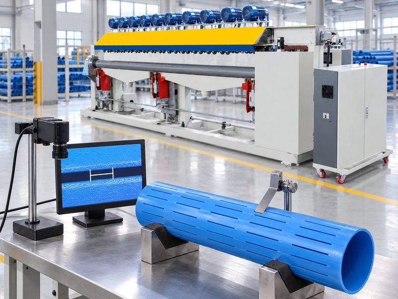
Measure plastic pipe slot width at the surface and locations specified by the drawing, using a method suited to the opening and tolerance. Take readings perpendicular to the local slot direction, without spreading the edges, and sample different axial positions, circumferential rows, and production stages.
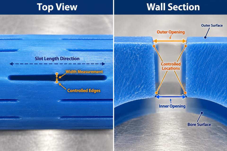
Before inspecting, agree on what “width” means. A blade thickness, a visible outside gap, and the narrowest passage through the wall can describe different quantities.
Define Which Slot Width the Drawing Controls
The inspection method must follow the finished opening requirement. Do not start with an available gauge and assume that whatever it checks is the specified dimension.
Clarify these points:
- Measurement surface:Outside opening, inside opening, or a defined through-wall condition.
- Direction:Across the slot, perpendicular to its local length direction.
- Longitudinal position:Which parts of the slot are included, and whether rounded ends are excluded.
- Acceptance limits:Nominal value, permitted variation, and treatment of local departures.
- Edge condition:How burrs, chamfers, and irregular edges affect measurement and acceptance.
For a transverse slot, the pipe surface curves along the opening. Set the viewing and contact direction locally rather than measuring an arbitrary projected gap.
When specifying custom slot dimensions on a pipe slotting machine, supply the measurement definition with the drawing. This allows production trials and incoming inspection to evaluate the same feature.
Blade thickness is useful tooling information, but runout, edge condition, pipe movement, and material response can affect the finished opening. Verify the product instead of accepting the cutter marking as its measured width.
Prepare the Pipe Without Changing the Opening
Preserve the condition being inspected. Cleaning away loose chips is different from removing attached burrs or reworking a slot edge.
Use a consistent preparation sequence:
- Identify the pipe, batch, and drawing revision.
- Let the sample reach the conditioning state required by the inspection procedure.
- Remove loose debris using the approved cleaning method.
- Record attached burrs or damage before any permitted finishing operation.
- Support the pipe without squeezing or bending the inspected section.
- Mark the axial and circumferential references.
Check whether acceptance applies before or after a specified deburring operation. Do not silently change stages between first-piece approval and routine inspection.
When evaluating the DS250-SA pipe slotting machine, include sample preparation and released-pipe inspection in the trial. A slot measured while tightly clamped may not represent its final condition.
Which Inspection Tool Fits the Slot And Tolerance?
Choose the method according to the required decision: checking a limit, recording a numerical width, or investigating the shape through the wall.
| Inspection Method | Suitable Task | Main Limitation | Result to Record |
| Approved limit blades or dedicated gauges | Defined go/no-go acceptance | Does not provide a complete numerical profile; force and depth matter | Gauge identity, position, and pass/fail result |
| Calibrated thickness leaves | Bracket an accessible gap under a defined procedure | Stacking or forcing leaves can distort the opening | Leaf sizes, insertion condition, and location |
| Measuring microscope or optical system | Measure accessible edges and examine local variation | Curvature, focus, lighting, and edge selection affect results | Width, image, calibration, and measurement location |
| Approved section inspection | Investigate inside or through-wall geometry | Destructive preparation can alter the section | Section location, preparation, and measured features |
Use Limit Gauges for Defined Acceptance Checks
- Specify gauge geometry and its relationship to the drawing limits.
- Define the entry surface, orientation, and insertion depth.
- State the permitted contact method; never use force to make a gauge enter.
- Check gauge condition and cleanliness before use.
- Record acceptance as a limit check, not an invented exact measurement.
A gauge entering from outside can be stopped by a narrower region deeper in the wall. Unless the procedure defines that check, it may not establish the outside opening width alone.
Use Optical Methods When Edge Detail Matters
- Calibrate the system for the measurement arrangement.
- Align the selected surface with the intended measurement plane.
- Control lighting, focus, magnification, and edge-detection rules.
- Keep outside and inside edge images from being confused.
- Retain images when they help explain a disputed edge.
An ordinary caliper is not automatically suitable for a narrow slot. Confirm that its contacts can access the defined feature without wedging or measuring a chamfer.
For the DS114-SA automatic slotting machine, agree on a sample inspection method as part of the product discussion. Machine size coverage does not establish which gauge resolves the requested tolerance.
Where Should Measurements Be Taken on Each Pipe?
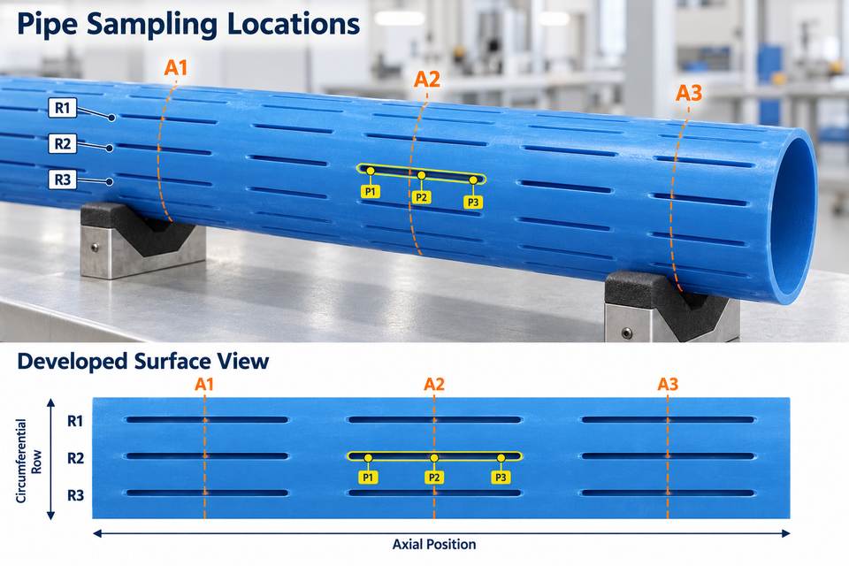
Use a location map so results can be repeated and related to the cutting process. “Three measurements on one pipe” is incomplete if all three come from the easiest top row.
Cover the required pattern:
- Start, middle, and end of the slotted region.
- Different circumferential rows or indexed positions.
- Defined positions along individual slots.
- Openings near unslotted ends and intermediate solid bands.
- Locations associated with cutting entry, exit, or restart.
- Different blade positions where a multi-blade head is used.
Keep pipe selection, slot selection, and point selection separate. The plan should state how many pipes are sampled, which slots are selected on each, and where each reading is taken.
A practical location code can combine pipe identity, axial station, row, and point. Keep the code consistent with the drawing and preserve the relationship to the blade or head position where traceable.
For custom blade arrangements and slot patterns, ask the supplier to identify which openings each blade produces. That mapping can distinguish one problematic cutter from a change affecting the whole machine.
How Should Sampling Cover the Production Run?
Sampling has different purposes at setup, during production, and at batch acceptance. Define each purpose before choosing frequency or quantity.
Confirm the First Piece After a Relevant Change
- New product or drawing revision.
- Blade replacement, sharpening, or head adjustment.
- Changed clamps, supports, or feed conditions.
- Restart after an interruption that could affect the setup.
First-piece approval should confirm the required positions and dimensions, not just a single convenient slot.
Monitor the Process And Accept the Batch Separately
- Use process checks to detect drift during the run.
- Record the production time and tool identity with each sample.
- Apply the agreed customer or product-specific plan for batch acceptance.
- Increase inspection or contain product after an abnormal result as required by the procedure.
- Review sampling when the material, pattern, or process changes.
The required sample size varies with the pipe and its specified tolerances. Set quantity and frequency using the product requirement, process history, and approved sampling plan.
Do not interpret a few passing locations as proof that every opening passes. Where acceptance is statistical, keep the sampling basis and decision rule explicit.
How Can Inspectors Separate Product Variation From Measurement Variation?
Before adjusting the machine, check whether different results come from different measurement conditions.
Use a marked location and compare:
- Repeated readings by one inspector.
- Readings by another inspector using the same procedure.
- Gauge condition, calibration status, and suitability for the tolerance.
- Sample orientation and support.
- Contact force or optical edge selection.
- Exact measurement surface and position.
Suppose one inspector reports acceptance and another reports rejection on the same slot. First confirm that both checked the same location and depth. One may be evaluating the outside mouth while the other contacts an inner restriction.
For numerical measurements, instrument resolution alone does not establish measurement capability. Review repeatability and relevant uncertainty, especially near an acceptance limit, and apply the agreed decision rule.
If the method cannot reliably distinguish the required limits, improve the method before using its readings to justify small machine adjustments.
How Should Slots outside Tolerance Be Handled?
Preserve the finding and confirm it through the approved procedure. Do not repeatedly measure until a passing number appears.
Follow a controlled response:
- Retain the sample and mark the failed location.
- Verify the drawing, gauge, method, and conditioning requirements.
- Recheck as specified, keeping the original result.
- Hold potentially affected products.
- Use production records to establish the investigation boundary.
- Inspect tooling, runout, holding, support, and chip interference.
- Make a documented correction and repeat first-piece approval.
- Disposition the affected batch under the agreed rules.
Do not average away a local failure when the requirement applies to individual widths. An acceptable mean can coexist with openings outside both limits.
Blade wear is one possible cause, not the only one. Correlate the defect with blade position, pipe location, and time before deciding what to replace or adjust.
What Should a Slot-Width Inspection Record Include?
Keep the record compact enough for production use but complete enough to reconstruct the decision.
- Product identity:Material, diameter, wall specification, pattern, and drawing revision.
- Production identity:Batch, date, time, machine, and tool group.
- Sample location:Pipe number, axial station, row or blade position, and within-slot point.
- Measurement method:Gauge or instrument identity, calibration status, and procedure revision.
- Sample condition:Cleaning stage, conditioning, and support arrangement.
- Results:Actual readings or limit-gauge outcomes, with units where applicable.
- Acceptance:Required limits, decision rule, and disposition.
- Follow-up:Rechecks, held product, adjustments, and release authorization.
Record limit-gauge outcomes as such. A pass/fail check should not be entered into a numerical trend chart as though an exact width had been measured.
Use the same dimensional definition for the equipment trial, routine inspection, and customer acceptance. When surface, location, gauge, and sampling agree, slot-width results become useful evidence for both product release and process control.