
Thread pitch and feed rate work together through the axial distance travelled during each relative revolution of the tool and pipe. For a single-start thread, that distance equals the pitch; for a multi-start thread, it equals the lead. Changing rotational speed therefore requires a corresponding change in axial speed if the same thread geometry is to be preserved.
The examples here describe the kinematics of thread turning, where relative rotation and axial motion generate a helix. They are explanatory calculations, not cutting-speed recommendations or machine programs. A dedicated threading machine may implement those motions through a different mechanical arrangement.
What Must Be Distinguished Before Doing the Arithmetic?
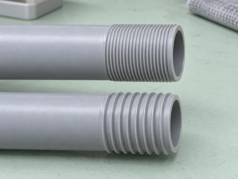
Pitch, lead and feed describe related but different quantities. To read pitch from a longitudinal section, choose a feature on one thread ridge and measure parallel to the pipe axis until that same feature appears on the neighbouring ridge. Lead is the axial advance along one helix during a complete revolution.
- Single-start thread: one continuous helix, with lead equal to pitch.
- Multi-start thread: several independent spiral paths share the surface; following one path through a full turn advances across as many pitch intervals as there are starts.
- Axial feed rate: distance travelled along the pipe axis per unit of time.
- Rotational speed: relative revolutions of the cutting motion per unit of time.
A thread’s profile, handedness, diameter and taper are additional geometric features. Matching pitch alone does not make two threaded parts compatible. Our guide to plastic pipe thread standards discusses the broader specification context.
There is also an important difference between axial feed and radial infeed. Axial feed follows the thread along the pipe, while radial infeed changes how deeply the tool engages the material. Increasing cutting depth is not the same operation as increasing pitch.
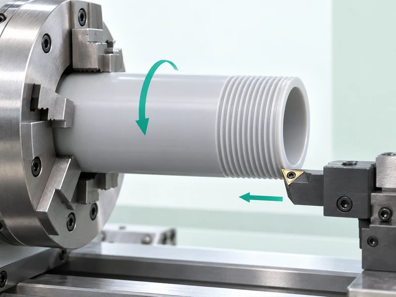
How Far Must the Tool Travel During One Revolution?
It must advance by one lead along the pipe axis. Consider an illustrative straight, single-start thread with a 3 mm pitch. After one revolution the axial position has changed by 3 mm, after two by 6 mm, and after ten by 30 mm.
Now imagine marking one starting point on the pipe and following the cut around it. The cut returns to the same angular position once per revolution, but at a different axial position. That combined movement creates the helix rather than a series of separate circular grooves.
The relationship is geometric, so it applies regardless of whether a particular machine rotates the pipe or rotates the cutting assembly around it. What matters is the relative motion. The machine architecture determines how that relationship is achieved.
This also explains the distinction between a thread and a circumferential groove. A groove can remain at one axial position throughout a rotation; a helical thread advances. Our comparison of pipe threading and pipe grooving explores their different functions.
What Does a Worked Feed-Rate Example Look Like?
During one minute, every completed relative turn contributes another lead-length of axial travel, so the accumulated distance depends on both the helix geometry and how many turns occur. For the hypothetical 3 mm single-start thread, 120 revolutions per minute corresponds to 360 mm of axial travel per minute. The units are what make the calculation unambiguous.
Axial speed in mm/min = lead in mm/revolution multiplied by rotational speed in revolutions/minute.
The following examples deliberately keep the arithmetic simple. They do not identify a suitable operating speed for any PVC, PP or PE grade, pipe diameter or Yuyu machine.
| Thread Geometry | Relative Speed | Required Axial Speed |
| Single start, 3 mm pitch, 3 mm lead | 120 revolutions/minute | 360 mm/min |
| Single start, 3 mm pitch, 3 mm lead | 180 revolutions/minute | 540 mm/min |
| Single start, 2 mm pitch, 2 mm lead | 120 revolutions/minute | 240 mm/min |
| Two starts, 3 mm pitch, 6 mm lead | 120 revolutions/minute | 720 mm/min |
The first two rows describe the same helix at different speeds. The third changes the thread spacing, while the fourth changes the number of starts. Treating all four as a simple choice of faster or slower feeding would miss those geometric differences.
How Long Does a Cutting Pass Take in This Example?
At 360 mm/min, axial motion is 6 mm per second. A 36 mm working travel would therefore occupy six seconds at that constant speed. At 540 mm/min, the same travel would occupy four seconds.
These are ideal travel times for the stated distance, not total machine cycles. Approach, acceleration, tool withdrawal, return, additional passes and pipe handling all add time. A two-second reduction in this one movement cannot be presented as a two-second reduction in every production cycle.
What Happens If Only One Speed Changes?
The generated lead changes if axial speed and rotational speed no longer maintain their intended ratio. Suppose axial motion remains at 360 mm/min while rotation rises from 120 to 180 revolutions/minute. The resulting advance is 2 mm per revolution instead of 3 mm.
Reversing the situation produces the opposite geometric change. If axial speed rises to 540 mm/min while rotation remains at 120 revolutions/minute, the advance becomes 4.5 mm per revolution. Neither motion describes the original 3 mm lead.
These examples show why a threading feed is not simply a general productivity control. A synchronized system must preserve the specified relationship while executing the cut. What an operator can change, and when, depends on the controller and the machine builder’s implementation.
Can Feed per Revolution Avoid Unit Confusion?
Expressing the motion as distance per revolution makes the geometric target explicit. Expressing it as distance per minute describes a speed that only matches that target at a particular rotational speed. The two descriptions are connected, but their numbers are not interchangeable.
A value of 3 in a distance-per-revolution field and a value of 3 in a distance-per-minute field represent very different movements. The explanatory formula should not be copied into an unfamiliar control screen without its units. Machine-specific instructions determine how the intended lead is entered.
How Do Repeated Passes Follow the Same Helix?
Each pass must retain the intended relationship between angular position and axial position. Repeating the same average speeds is not enough if the next pass starts at a different phase. The tool would then encounter material beside the existing groove instead of deepening the same thread path.
As one documented controller example, LinuxCNC’s spindle-synchronized motion uses distance per revolution and a spindle index reference to align repeated passes. Its documentation also discusses acceleration during synchronization. This illustrates a control principle, not a claim that Yuyu equipment uses LinuxCNC or that its command syntax applies to another controller.
During successive cuts, the tool’s engagement can change while the lead remains fixed. That separation allows material to be removed progressively along the same helix. The chosen infeed method and final profile belong to the tooling and process design.
In plastic pipe machining, this movement also takes place in a material that can deflect or retain heat. A geometrically synchronized path does not by itself guarantee a clean surface. Tool condition, support and chip removal during plastic pipe threading still influence what the finished surface looks like.
Where Do Diameter, Taper and Thread Form Enter the Picture?
Diameter affects the circumferential distance covered in each revolution, even when lead is unchanged. Two pipes turning at the same rotational speed can therefore have different surface speeds. This is one reason the example rotational speeds cannot be promoted as universal cutting settings.
A tapered thread also requires radial position to change along the axial travel. Its axial lead must be distinguished from distance measured along a sloping tool path. The controller’s definitions and the specified thread geometry determine how those movements are coordinated.
Yuyu’s DS250-TS automatic thread cutting machine lists T-thread production. That product description identifies a thread-form application; it does not specify a universal lead, number of starts or control algorithm. Those details must come from the actual product drawing and machine configuration.
How Can the Required Pipe Thread Geometry Be Translated Into Coordinated Cutting Motion?
Start with the required helix, then translate it into coordinated motion. Establish pitch and number of starts to obtain lead, and relate that lead to the chosen relative rotational speed. Keep axial speed, radial infeed and total cycle time as separate quantities.
The Yuyu pipe threading machine range provides equipment context for producing threaded pipe ends. The underlying principle remains simple: a faster revolution needs a correspondingly faster axial advance to preserve the same lead. That relationship explains the geometry while leaving material-specific cutting conditions to the appropriate production process.