
Chip removal matters in plastic pipe threading because material left near the cutting edge can interfere with the next cut, rub against the pipe and mark the newly formed thread. Accumulated chips can also obstruct the tool path or remain inside the bore. Effective removal keeps the cutting zone clear and helps the process behave consistently from one pipe to the next.
The correct method depends on the plastic, thread profile, cutting tool and machine layout. This article addresses factory machining of plastic pipe threads rather than treating every threading machine as if it used a metal-pipe die head.
What Happens When Chips Stay in the Cutting Zone?
Chips are detached material, but they can still influence the surface being produced. A piece caught between the tool and the pipe may be cut again, dragged across a thread flank or pressed into a softer region. The result can be a rough patch that is not explained by thread pitch alone.
MIT’s introduction to machining physics explains the general importance of allowing chips to leave the work area without tangling or interfering with the cut. Its examples also connect trapped chips with additional rubbing and heat. Those principles are useful here, although the exact removal method must suit plastic pipe and the installed tooling.
Threading creates a repeated profile, so a chip can affect more than one adjacent surface as cutting continues. A small obstruction that would be easy to remove from a flat part may become lodged between thread turns. Keeping the region clear is therefore part of producing the geometry, not merely cleaning up afterward.
Why Can Plastic Chips Be Difficult to Manage?
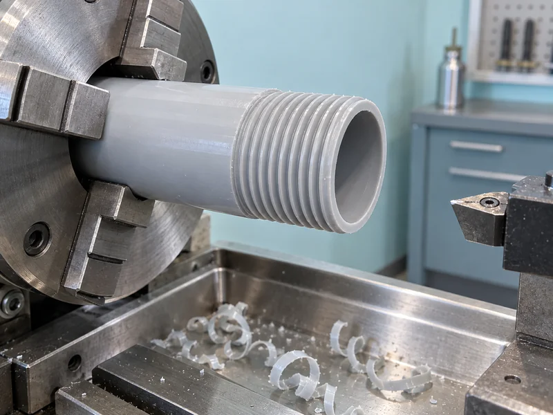
Plastic chips may form ribbons, curls, fragments or fine particles depending on the material and cutting conditions. Long flexible strips can wrap around a tool or bridge an extraction opening. Small fragments can settle in thread roots, while fine particles may spread beyond the immediate cutting area.
Chip appearance is a clue, not a standalone verdict on quality. A change in shape can accompany a different material batch, tool condition, cutting engagement or temperature. Compare it with the finished surface and the process settings before deciding what to adjust.
Our comparison of plastic and metal pipe threading requirements gives useful context. A method that clears heavy metal chips efficiently may not control light, flexible plastic swarf in the same way.
How Does Poor Chip Removal Affect Thread Quality?
Poor removal can create surface damage, inconsistent cutting conditions and misleading impressions of a tooling problem. The important question is where the chips travel after separation. They should leave the active region rather than circulate through it again.
Why Do Scratches Appear on Freshly Cut Threads?
A trapped chip can move across a surface that the tool has already finished. Depending on its shape and the local load, it may leave a scratch or an irregular mark. If marks become more frequent as swarf accumulates, compare the chip path before changing the thread dimensions.
Can Chip Buildup Contribute to Smearing?
It can contribute by adding rubbing or disturbing the cutting action, but smearing has several possible causes. A dull edge, unsuitable engagement or excessive local heating may also be involved. Removing chips does not restore a damaged tool or correct an incompatible cutting recipe.
Distinguish adhered material from an actual change in the thread profile. A root that contains loose swarf may appear shallower than it is. Conversely, a clean-looking surface can still have the wrong pitch or form; our guide to plastic pipe thread standards covers the separate geometric requirements.
What Makes a Chip-Removal Path Effective?
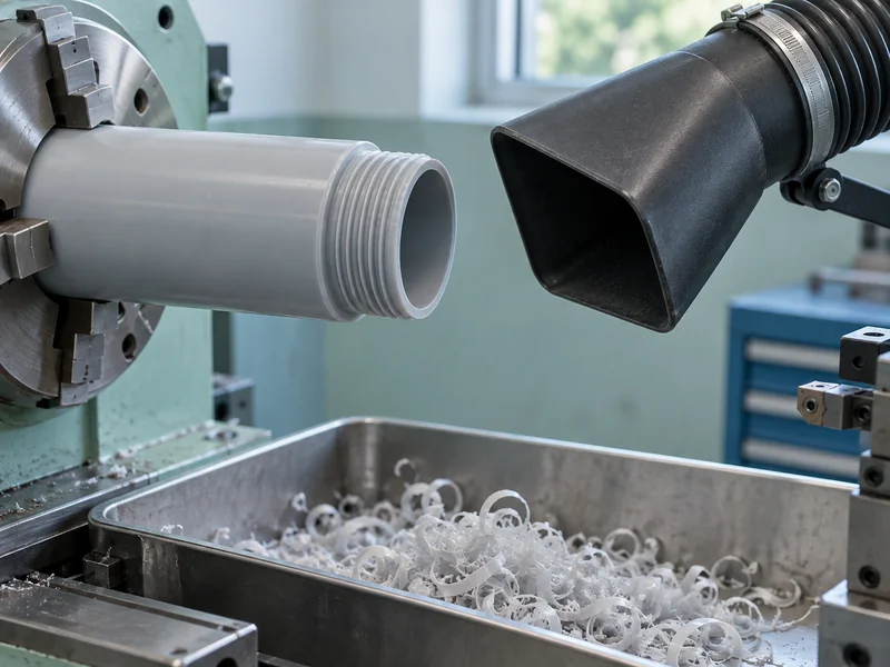
An effective path starts near the source and continues through collection without a place for material to accumulate and return. Capture location matters as much as the nominal capacity of the extraction device. The arrangement also has to accommodate movement of the pipe and tool throughout the cycle.
| Location | Possible Interference | Process Focus |
| Cutting edge | Chips enter the following cut | Direct removal close to the point of generation |
| Thread root | Loose material remains between turns | Check the clearing path along the full thread |
| Pipe bore | Internal chips collect out of view | Include bore clearing in the cycle |
| Hood or duct | Ribbons bridge or restrict the opening | Maintain suitable clearances and access |
| Collection container | A full container disrupts removal | Use a defined emptying and maintenance routine |
External and internal threading can require different arrangements. On an external cut, gravity may help material fall away, depending on orientation. Inside a pipe end, the surrounding bore can restrict access and retain swarf even when the outside appears clear.
The Yuyu DS250-TS automatic thread cutting machine is listed for T-thread production. A product’s thread designation does not establish its chip-removal configuration, so any attachment or setting must match the actual machine supplied.
Should the Process Use Extraction, Air or Coolant?
Use the method specified for the equipment and compatible with the plastic and application. Extraction can collect material near its source, while a properly designed air arrangement can help guide chips toward collection. A liquid system introduces additional compatibility, separation and drying considerations.
Do not assume a coolant used for metal machining is suitable for the plastic being processed. Tom Rohlfs’s guide Understanding the Art of Machining Plastics, hosted by the University of Virginia, discusses the possibility of incompatible fluids damaging plastic components. Confirm compatibility with the specific material and application before introducing a new fluid.
An air jet that merely blows chips across the machine can relocate the problem instead of collecting the material. Its direction should support the intended capture path without spreading debris toward operators or other equipment. Any change should stay within the machine’s documented operating arrangements.
How Are Tool Condition and Chip Removal Connected?
The cutting edge influences the shape and direction of the departing material. A worn or contaminated edge can alter that behaviour, making a previously stable removal arrangement less effective. Conversely, persistent recutting of accumulated material can disturb the tool’s working conditions.
Investigate both sides of this relationship. If removal deteriorates immediately after a tool change, review the installed geometry and position. If it deteriorates gradually during a run, compare tool condition with the state of the capture and collection system.
- Check whether the chip path changes at a particular point in the tool travel.
- Look for material adhering to the cutting edge after the machine is safely stopped.
- Compare external thread cleanliness with material remaining in the bore.
- Keep tools and collection areas free of debris from previous jobs.
- Record adjustments so the next shift can reproduce the working arrangement.
What Can a Controlled Troubleshooting Sequence Reveal?
A controlled sequence helps distinguish buildup from other causes of rough threads. Begin with a clean machine and the established recipe, then observe how the condition changes through normal production. Stop and isolate equipment as required before clearing obstructions or accessing the cutting area.
Consider an illustrative run where the first pipe is clean but later pipes develop scattered marks. If the marks disappear after restoring a blocked collection path while other settings remain fixed, chip accumulation becomes a plausible contributor. This is stronger evidence than simultaneously changing the speed, tool, feed and extraction arrangement.
If the first pipe is already rough, do not assume that a larger extraction unit will fix the problem. Review the tool edge, pipe support, material and cutting engagement as well. Our article on common pipe threader problems places chip-related symptoms among other possible causes.
How Does Removal Influence Continuous Production?
Continuous production needs the collection system to remain effective beyond the first successful cycle. A clean first piece cannot demonstrate that a duct will stay clear or a container will hold an entire shift’s waste. Plan the clearing and collection routine around the actual material generated.
A slightly shorter cutting cycle may offer little benefit if it causes frequent interruptions to remove wrapped swarf. Compare sustained usable output and cleaning interruptions together. This gives a more informative picture than viewing spindle time alone.
What Is the Most Useful Operating Principle?
Make chip movement part of the threading process from the cutting edge to the collection point. Keep the tool suitable, the pipe supported and the removal path clear, then investigate any change in chip behaviour alongside the finished surface. These controls support repeatability without replacing the separate requirements for thread dimensions and material suitability.
Yuyu’s pipe threading machine range provides the equipment context for different production needs. Across configurations, the same principle applies: once material has been removed, prevent it from interfering with the surface being made.