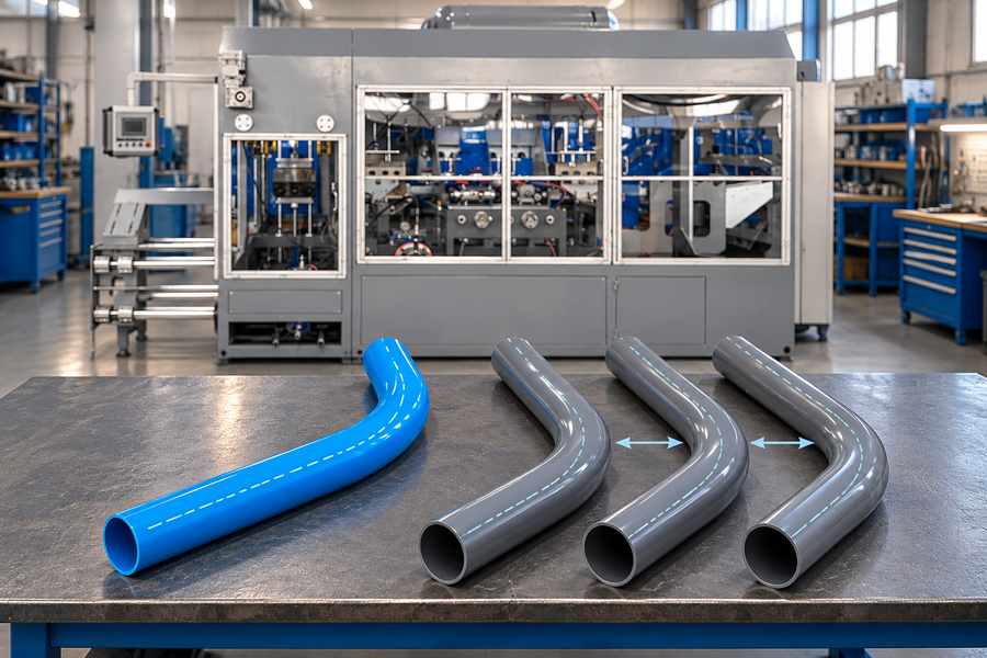
Lane spacing sets the distance between neighboring pipe-processing centerlines. Its adequacy depends on pipe size, tooling width, bend movement, and the space occupied during release.
Single-pipe layouts avoid neighboring lane conflicts, while multi-pipe layouts require clearance across simultaneous operations. Buyers need dimensioned drawings and representative trials before approving the quoted arrangement.
What Is Lane Spacing in a Pipe Bending Machine?
Centerline Pitch and Usable Clearance Are Different Measurements
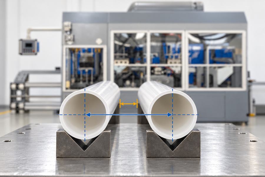
Lane pitch is measured between the centerlines of adjacent pipe paths at a specified machine reference position. Without that reference, two drawings can describe different distances using the same term.
A pipe-to-pipe gap describes the distance between their outside surfaces at one position. Tool-to-tool clearance instead concerns clamps, heaters, molds, guides, and any moving equipment occupying adjacent lanes.
For two straight pipes of equal outside diameter, the nominal surface gap equals centerline pitch minus that diameter. This simple relationship stops describing available clearance once tools or bends extend sideways.
The narrowest usable gap may appear halfway through forming, during mold withdrawal, or while an operator removes a finished bend. A static drawing of straight pipes cannot reveal every restriction.
Measurements Needed Before Comparing Layouts
Start with the actual pipe range: specified outside diameters, permitted dimensional variation, wall thicknesses, and bend configurations. Wall thickness affects processing behavior but does not directly substitute for an external clearance measurement.
Record the widths and offsets of clamps, heating assemblies, forming molds, supports, and guides. These dimensions must come from the quoted tooling arrangement, not a general product description.
Define leftward and rightward occupied widths from each lane centerline. Include moving components, the pipe’s changing shape, and the intended removal path rather than treating finished-part dimensions as sufficient.
Where lane pitch is adjustable, request the supported adjustment positions and the means of locating each lane. Adjustable spacing is a quotation-specific feature, not an assumed machine capability.
Agree how clearances will be measured: between which surfaces, at which cycle stage, and with what machine condition. Otherwise, a recorded gap may be impossible to reproduce.
How Does Selection Differ Between Single-Pipe and Multi-Pipe Layouts?
A Single Lane Still Needs a Full Working Envelope
A single processing path removes the possibility of contact with a second pipe being bent beside it. However, the bend can still approach the frame, guards, nearby equipment, or discharge area.
Tool access matters when clamps or molds need replacement. A generous open side may shorten an awkward changeover, but the advantage depends on the actual machine layout and access arrangement.
For a single-lane quotation, ask for the largest permitted bend envelope and its distance from surrounding structures. Do not accept an illustration showing only a straight incoming pipe.
Multiple Lanes Add Interaction Between Moving Envelopes
In a multi-lane arrangement, neighboring components may compete for the same lateral space. Opposing bend directions can create a tighter condition than bends traveling away from one another.
Even if all lanes begin with ample straight-pipe clearance, their tooling and finished shapes may overlap during the cycle. Check whether neighboring parts or tools occupy the same clearance zone during any shared stage of the cycle.
Separate control of individual lanes, staggered movements, and independent tooling are possible design approaches only when confirmed in the quotation. None can be presumed from the requested lane count.
A comparison also needs accepted parts over a defined observation period. More lanes alone establish neither simultaneous operation nor a proportional increase in usable production output.
Request a sequence chart if adjacent lanes share equipment or operating time. It can reveal whether one lane must pause while another finishes forming or releases its part.
| Buyer comparison | Single-pipe layout | Multi-pipe layout |
| Main clearance concern | Pipe, tools, and bend versus surrounding equipment | Those same constraints plus neighboring lane envelopes |
| Forming sequence | One processing path to validate | Confirm simultaneous or staggered lane operation |
| Tool access | Verify reach around one tool set | Check access to interior and outer tool positions |
| Changeover | Confirm replacement space and settings | Check whether one change affects adjacent lanes |
| Output evidence | Accepted parts per measured period | Accepted parts per period, including lane stoppages |
Which Factors Establish the Required Pitch?
Pipe Size and the Widest Tooling Component
The pipe outside diameter establishes only one portion of the occupied envelope. A clamp jaw, heater housing, or forming mold may extend farther sideways than the pipe itself.
Identify the largest outside diameter permitted by the purchasing specification, not just its nominal designation. Include relevant ovality or dimensional limits when determining where the pipe surface might reach.
Compare this pipe envelope against drawings for each intended tooling set. A pitch adequate for the smallest product can become unusable after switching to a wider mold or clamp.
Ask which item fixes the minimum separation: pipe surfaces, tool bodies, support hardware, or movement stops. Knowing the limiting item makes any proposed spacing change easier to assess.
Bend Geometry and Direction of Movement
Bend angle, centerline radius, heated length, and tooling motion affect where material and equipment travel. Their combined envelope matters more than the finished bend’s overall dimensions alone.
For adjacent lanes, distinguish bends moving in the same direction from bends approaching each other. The nearest surfaces may change throughout the cycle even when both parts share nominal geometry.
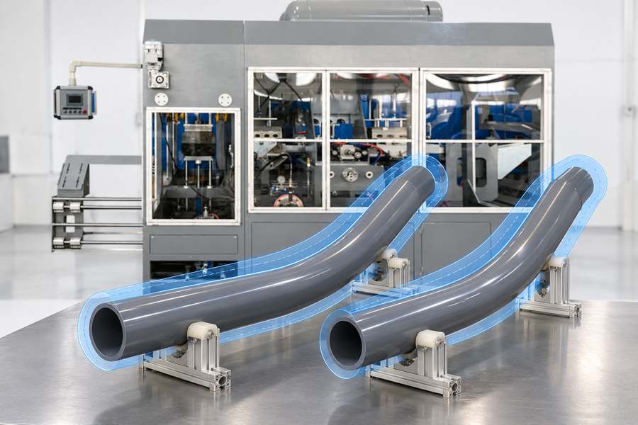
Request a swept-envelope drawing showing relevant intermediate positions, including maximum lateral excursion. If the configuration uses different sequences by pipe size, each sequence needs its own clearance assessment.
The loading orientation also matters. A completed bend might clear its forming mold yet strike a neighboring support when lifted, rotated, or transferred toward the discharge position.
Check whether different products will run side by side. Mixed bend geometries can create asymmetric envelopes that a drawing of identical neighboring pipes would not expose.
Heating, Cooling, and Mold Withdrawal
Heating equipment can determine lane pitch before the pipe begins bending. Verify heater outside dimensions, approach motion, cable routing, and whether nearby assemblies create thermal interference under the quoted arrangement.
Yuyu Machinery’s pipe bending machine information describes infrared heating, internal air support, outer mold forming, and water cooling for a featured configuration. These details do not establish universal lane arrangements.
For any quoted machine using those processes, examine the actual positions of heaters, air connections, mold bodies, water lines, and associated moving parts. Do not assume identical envelopes across configurations.
Cooling and release deserve separate checks because a formed pipe may remain constrained after bending stops. A mold can clear the finished part only after sufficient withdrawal travel has occurred.
Ask whether removal requires sideways translation, rotation, vertical lifting, or a combination. A path that works with one pipe can obstruct a neighboring lane during simultaneous unloading.
Connections also need space at their tightest bend or travel position. Verify hose and cable clearances against moving assemblies, rather than measuring only their stationary mounting points.
How Should Lane Spacing Be Calculated and Specified?
Build a Clearance Budget Around Real Motion
Choose a common datum and draw each lane centerline. For a neighboring pair, measure the farthest rightward occupied extent of the left lane and the farthest leftward extent of the right lane.
At a given relevant operating condition, the preliminary requirement is:
Required pitch ≥ left-lane rightward extent + right-lane leftward extent + required clearance
All three terms must use consistent measurement conventions.
For a hypothetical illustration, assume extents of 80 mm and 90 mm and an agreed 20 mm clearance. Their sum gives a preliminary pitch of 190 mm, not a recommended machine specification.
The clearance allowance must be justified for the proposed configuration. Consider positioning variation, pipe dimensional variation, operating movement, and measurement uncertainty, documenting which factors already appear in the drawn envelopes.
Avoid adding the same variation twice. For example, if an envelope already represents the maximum permitted pipe diameter and alignment excursion, do not silently add those entire allowances again.
Repeat the calculation across meaningful process positions and product combinations. The governing pitch is the largest valid requirement, subject to trial confirmation and any machine-specific mechanical constraints.
A symmetrical width assumption is convenient but often wrong. Offset tooling or bends moving preferentially to one side require separate leftward and rightward measurements for each lane.
If neighboring lanes move at different times, document the actual sequence. A non-overlap argument based on timing is valid only when the quoted control arrangement and operating trials support it.
Require Drawings That Can Be Checked at the Machine
A useful layout gives lane centerlines, pitch dimensions, reference datums, and tolerances. It identifies whether measurements are taken at pipe entry, the forming station, or another defined location.
Plan views need tool outlines and swept bending envelopes; side views reveal vertical overlaps and removal restrictions. Include mounting points or reference features that inspectors can locate on the assembled machine.
Indicate maximum tooling widths, intended adjustment positions, and the routes of any connections occupying inter-lane space. Mark maintenance access separately from the clearance needed during automatic movement.
Each drawing revision must identify the pipe outside diameter, bend radius, bend angle, tooling set, and direction of movement it covers. Otherwise, approval may apply only to an unstated example.
Where an adjustable arrangement is requested, obtain a repeatable setup method and a means to verify actual pitch after changeover. Quoted adjustment travel alone does not demonstrate repeatable positioning.
Do not approve a drawing showing only the machine footprint. The procurement package needs the working envelopes, otherwise a smaller overall width can hide an impractical lane arrangement.
How Can Buyers Verify Spacing During Production Trials?
Test the Configurations That Challenge Clearance
Select trials from the planned production mix rather than relying on the visually largest pipe. A smaller pipe with a wider tool or different bend direction may create the tighter clearance.
Include the governing combinations identified by the envelope review. Record the pipe specification, tooling revision, programmed or set bend geometry, and actual lane positions before each run.
Observe feeding, positioning, clamping, heating, forming, cooling, tool withdrawal, and finished-part removal wherever those stages occur in the quoted process. Note the instant and location of minimum clearance.
For multi-pipe operation, repeat the checks with adjacent lanes active under the intended production sequence. An isolated single-lane demonstration cannot verify simultaneous-lane interference or shared access.
Do not infer process suitability from one successful cycle. Use an agreed representative run to expose repeatability problems, changeover effects, and restrictions that emerge only during continued operation.
After a product changeover, measure the pitch again and inspect the first acceptable bends. A setup that previously passed may no longer represent the new tool positions.
Separate Spacing Failures from Other Process Problems
Pipe scratches at matching lateral positions can suggest neighboring contact, but their location alone does not establish the cause. Inspect guide surfaces, tooling edges, and handling paths before changing pitch.
Incomplete bends or inconsistent shape may arise from temperature, support, geometry settings, or tooling conditions. Compare lane-specific records before treating every deviation as inadequate separation.
Tool collision, incomplete mold withdrawal, and finished bends catching during removal provide more direct evidence of envelope conflicts. Record the precise cycle stage rather than describing the entire machine as crowded.
If the supplier changes pitch, tooling offset, or movement timing, repeat the originally failed trial. Altering several settings together makes the corrective effect difficult to establish.
Keep Acceptance Records That Support a Decision
Before testing, agree on clearance locations, measurement methods, instrumentation, and acceptance limits appropriate to the quoted design. There is no universal minimum gap that suits every pipe and mechanism.
Use photographs or marked drawings to identify close approaches, alongside measured results when access permits. Record any observation that cannot safely be measured directly during machine movement.
| Test record item | Required observation or measurement | Purpose of the record |
| Product and setup | Pipe dimensions, bend geometry, tooling revision | Reproduces the tested configuration |
| Lane geometry | Specified pitch, measured pitch, datum | Checks actual setup against the drawing |
| Minimum clearance | Location, stage, measured or estimated gap, method | Locates the governing interference risk |
| Cycle behavior | Concurrent or staggered movement; stoppage reason | Tests the intended operating sequence |
| Part result | Accepted quantity, rejected quantity, defect description | Separates throughput from raw cycle counts |
| Corrective action | Setting or tooling change, retest identification | Demonstrates whether the issue was resolved |
Accepted output can be compared using the same observation period, product mix, inspection rules, and treatment of stoppages. Otherwise, a multi-lane result may appear better simply because trial conditions differ.
What Must Be Agreed with Yuyu Machinery Before Ordering?
Define the Quoted Capability Precisely
State the required number of processing lanes and the pipe and bend combinations intended for each. Request confirmation of their permitted simultaneous operation instead of assuming every combination can run together.
Specify whether pitch is fixed, adjustable, or changed by tooling replacement. If adjustment is offered, obtain its applicable positions, setup method, and constraints on adjacent processing operations.
Confirm the supplied heating, forming, cooling, and removal arrangement for each proposed configuration. Independent lane control, automated handling, and adjustable tooling remain optional possibilities until expressly included in quotation documents.
Ask for the limiting configuration and the resulting machine width, including usable access. A compact pitch that blocks essential tooling replacement may defeat the intended production benefit.
Tie Approval to Drawings and Tested Results
Obtain controlled layout drawings, tool-envelope information, and an agreed list of trial configurations before acceptance. The drawings must correspond to the machine and tools actually supplied.
Use the supplier’s service and technical discussion channel to settle measurement responsibilities, trial documentation, and corrective-action arrangements as part of the procurement discussion.
Approval records need specified and measured pitch, verified critical clearances, output and quality results, unresolved restrictions, and the drawing revisions used during testing. A general statement that lanes fit is insufficient.
If a restriction remains, identify the affected product or operating mode in the purchase agreement. Explicit limitations are more useful than treating one successful trial as approval for every configuration.
Select the pitch that accommodates the verified operating envelopes and the required accepted output. Available machine width and preferred lane count remain design constraints, not substitutes for clearance evidence.