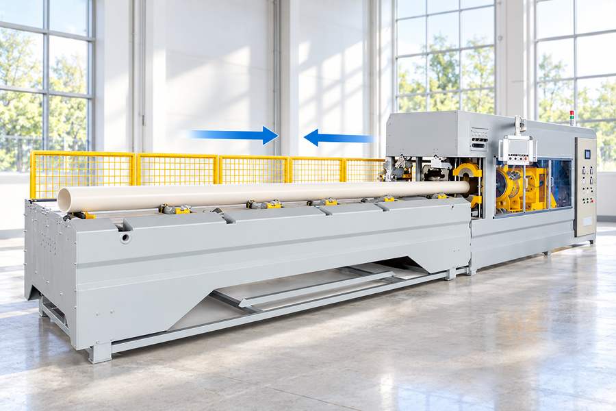
Forming stroke defines the travel needed to shape a pipe socket. Retraction stroke defines the movement needed to disengage tooling after forming. Neither dimension necessarily equals finished socket depth.
Reliable specifications begin with drawing datums, tooling positions, and release clearances. Buyers then verify those dimensions through measured trials before accepting a machine.
Define Forming and Retraction Strokes on Technical Drawings
A stroke specification is incomplete unless it identifies which component moves, where movement begins, and where it ends. These details establish the basis for evaluating machine travel.
Distinguish Forming Stroke from Retraction Stroke
The forming stroke describes movement between the specified starting position and final forming position of a particular tool. Its direction depends on the forming mechanism.
For axial mandrel forming, movement generally follows the pipe centerline. Equipment incorporating movable mold segments or expansion elements may also require separately defined radial travel.
Retraction stroke describes movement from a working position toward the position needed for tooling release. Depending on machine construction, this may involve axial withdrawal, radial opening, or coordinated movements.
These dimensions must remain separate from three related measurements:
- Socket forming length: The finished axial dimension of the shaped pipe region, measured from the specified drawing datum.
- Tool engagement depth: The distance a particular forming surface enters or engages the pipe during forming.
- Actuator travel: The physical movement of the driven mechanism, which may differ from tool displacement when mechanical linkages are involved.
The belling machine overview from Yuyu Machinery describes positioning, clamping, heating, forming, cooling, mold retraction, and ejection. The required stroke dimensions must still be established for the selected tooling configuration.
Establish Reference Datums and Stroke Endpoints
A drawing needs fixed references before any movement can be measured consistently. The pipe-end plane, pipe centerline, and defined clamping reference provide useful starting points.
For each moving tool, identify the initial position, final forming position, and fully released position. Dimension these locations against the selected fixed datum.
Avoid defining movement only as “forward” or “backward.” Such descriptions become ambiguous when tooling orientation changes or when multiple mechanisms operate along different axes.
| Movement | Drawing reference | Required endpoint definition |
| Axial forming | Pipe-end plane and fixed machine datum | Initial tool position and final forming position |
| Radial forming | Pipe centerline and tool reference surface | Open position and final forming position |
| Axial retraction | Final forming position and fixed datum | Tool position providing specified release clearance |
| Radial mold opening | Mold centerline and segment reference | Released position and minimum clearance |
| Ejection or transfer | Pipe position and surrounding tooling | Required movement envelope after tooling release |
Identify Separate Movements on Assembly Drawings
The tooling drawing should show the operating positions together with the surrounding clamps, guides, supports, and moving assemblies. This makes potential interference easier to identify.
Where several components move independently, assign each movement its own stroke dimension. A single overall travel value cannot describe the required coordination between different axes.
Calculate the Required Forming Stroke from Socket Geometry
Forming stroke selection begins with the finished socket drawing, but requires additional information about tooling geometry and initial positioning before a usable machine travel value can be established.
Relate Socket Dimensions to Axial Tool Travel
Review the specified socket depth, entrance profile, transition region, and any internal groove features. These dimensions determine which areas of the pipe require forming contact.
Next, identify the tool surfaces responsible for producing those features. The final position of these surfaces establishes the required engagement relative to the pipe-end datum.
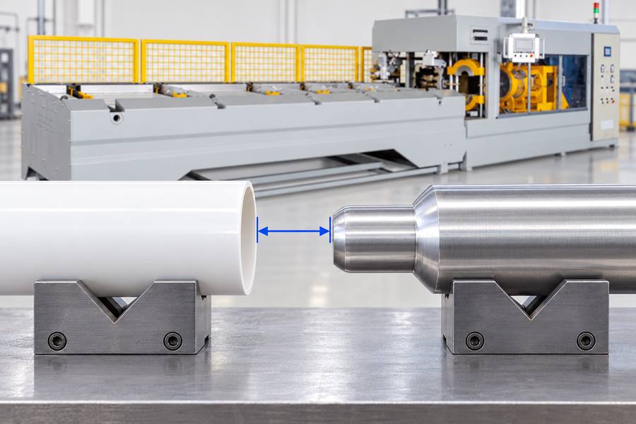
The starting position must also be defined. A mandrel positioned outside the pipe needs sufficient forward movement to close the initial gap before reaching its final forming position.
Consequently, axial forming stroke is not automatically equal to socket depth. The difference depends on starting clearance, tooling geometry, and the selected reference surfaces.
Use a Drawing-Based Stroke Calculation
Consider a hypothetical drawing in which a mandrel reference point starts 18 mm before the pipe-end plane and finishes 72 mm beyond that plane.
With a stationary pipe datum and direct linear movement, the hypothetical axial travel would be:
Forming stroke = 18 mm + 72 mm = 90 mm
These figures are illustrative calculation assumptions, not specifications or measured performance values for any Yuyu Machinery machine.
The calculation establishes nominal travel between two reference positions. It does not establish the required actuator capacity, positioning tolerance, or clearance around adjacent tooling.
If a linkage changes the relationship between actuator displacement and mandrel movement, that mechanical relationship must also appear in the supplier’s calculation.
Account for Tooling Geometry and Pipe Position
Mandrel shoulders, tapered transitions, forming surfaces, and locating features influence where the tool must stop. The finished socket profile cannot define these relationships independently.
Pipe positioning introduces another variable. Differences in clamping position or pipe-end preparation may alter the effective engagement even when the actuator reaches the same endpoint.
Review the following conditions for the quoted application:
- Pipe outside diameter and ovality: Confirm that the permitted incoming geometry can be accommodated without unintended interference.
- Wall thickness: Check whether the intended forming profile remains achievable across the specified wall-thickness range.
- Heating condition: Establish the material condition required for proper forming rather than using actuator travel to compensate for inadequate heating.
- Tool alignment: Verify that the mandrel and pipe centerline relationship is maintained during engagement.
- Initial clearance: Confirm that the tool can approach without contacting clamps, guides, or incorrectly positioned pipe ends.
These checks may reveal an adjustment requirement rather than a need for greater nominal stroke.
Define Final Forming Position and Adjustment Range
For each socket configuration, specify the intended final tool position and its allowable variation. The acceptance tolerance must come from the agreed design requirements.
Where different sockets require different positions, identify the necessary adjustment range. Also establish whether that range is achieved through tooling changes, mechanical adjustment, or controlled positioning.
Working stroke and maximum available machine travel are different specifications. The quoted equipment must accommodate the required working positions without relying on travel beyond its usable limits.
Determine Retraction Stroke and Mold Release Clearance
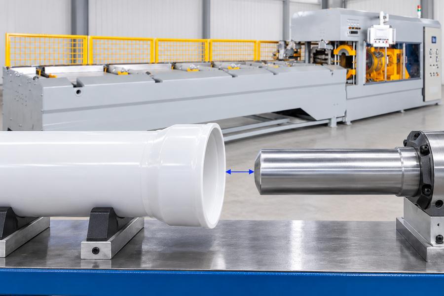
Retraction stroke must provide enough movement to disengage the tooling without damaging the formed socket. Its required length depends on actual tool geometry and the release sequence.
Calculate the Minimum Tool Withdrawal Distance
Begin at the final forming position. Identify every feature that must disengage before the pipe can be removed or transferred.
For axial tooling, check mandrel shoulders, projecting profiles, tapered surfaces, and any features extending into formed grooves. The critical feature may not be the mandrel tip.
Determine the withdrawal position at which the complete tooling envelope clears the surfaces that could obstruct release.
The required withdrawal distance is measured between this position and the final forming position. Additional travel may be necessary when the machine’s next movement requires more clearance.
Do not introduce an arbitrary extra stroke without identifying its purpose. Excessive travel can increase cycle movement and create additional space requirements without improving release.
Coordinate Axial Retraction and Radial Mold Opening
Some tooling arrangements use separate mechanisms for axial withdrawal and radial mold opening. Their movement sequence can influence both the required stroke and available clearance.
For example, a projecting groove-forming feature may need to withdraw from the socket wall before another component moves axially. The actual sequence depends on mold construction.
The supplier’s assembly drawing should therefore indicate which movements can overlap and which require completed release before subsequent movement begins.
Questions to resolve include whether axial withdrawal can begin before full radial opening, whether the pipe remains clamped during withdrawal, and which position permits ejection.
Check Clearance Under Actual Release Conditions
The formed pipe does not necessarily retain the same dimensions throughout heating, forming, and cooling. Material contraction and local deformation can change contact conditions.
Release clearance must therefore be evaluated against the expected socket condition at the specified withdrawal point, not simply the cold tooling drawing.
Possible indications of insufficient clearance include:
- Drag marks: Contact between the withdrawing tool and the formed socket surface.
- Socket distortion: Local deformation appearing during withdrawal rather than during initial forming.
- Incomplete release: A tool reaches its indicated endpoint but still obstructs pipe movement.
- Intermittent sticking: Release behavior changes with pipe dimensions, cooling condition, or tooling temperature.
When these problems appear, investigate their physical causes before increasing retraction stroke. Incorrect alignment, damaged tooling, or an unsuitable release sequence may be responsible.
Check Stroke Compatibility with Machine Travel and Position Controls
The calculated working strokes must fit the selected machine arrangement. This requires checking usable travel, mechanical limits, adjustment capability, and position verification.
Compare Required Stroke with Available Machine Travel
Request the usable stroke for each relevant actuator rather than relying only on its nominal rated travel.
The usable range must account for installed tooling, end stops, mounting geometry, and any positions reserved for mechanical clearance.
At the forming endpoint, confirm that the mechanism has sufficient usable travel to reach the required working position without bottoming out against an unintended limit.
At the retraction endpoint, check whether the tooling fully clears the pipe and whether the next required operation has an unobstructed movement path.
These checks should cover the intended range of tooling configurations. A setup suitable for one socket size may restrict available travel after a mold change.
Verify Stroke Adjustment and Position Monitoring
Different mechanisms may establish endpoints through mechanical stops, position sensors, or controlled actuator movement. The selected method determines how settings are adjusted and verified.
For the quoted configuration, confirm the following capabilities:
- Adjustment method: How operators establish forming and retraction endpoints for the approved tooling.
- Position indication: Whether the relevant working positions can be measured or displayed.
- Repeatability: Whether repeated movements return to positions within the agreed acceptance limits.
- Travel limits: How movement is prevented from exceeding the permitted mechanical range.
- Setup retention: How approved settings are identified or restored after a tooling change.
These are purchase questions, not assumed standard features of Yuyu Machinery equipment.
Check Movement Sequencing and Fault Detection
The control sequence must correspond to the tooling’s physical release requirements. A correct stroke dimension alone cannot prevent interference caused by incorrect movement timing.
Confirm how the quoted control arrangement establishes completion of forming, cooling, retraction, and ejection movements before permitting dependent actions.
Also define the required response to incomplete movement. A mechanism that stops short of its release position should not automatically be treated as ready for pipe removal.
Verify Forming and Retraction Strokes Through Acceptance Testing
Drawing approval establishes the intended movements. Acceptance testing checks whether the installed tooling reaches those positions consistently and produces sockets meeting the agreed requirements.
Measure Actual Travel Before Heated-Pipe Trials
Begin with movement checks under the agreed test conditions. Identify the same reference positions used on the approved assembly drawing.
Use a suitable independent measurement method where practical. Compare the measured movement with the indicated position instead of assuming that a control setting represents actual tool travel.
Record the starting position, final forming position, fully retracted position, and measured displacement for each relevant axis.
Repeat movements to identify inconsistent stopping positions, abnormal mechanical resistance, or changes associated with direction reversal.
Initial checks also provide an opportunity to observe possible interference between moving tooling, clamps, and guides before testing heated pipe.
Test Representative Pipes and Socket Configurations
Heated-pipe trials should cover the configurations identified in the purchase specification. These may include different pipe sizes, wall thicknesses, or socket geometries.
Record the actual pipe material, incoming dimensions, tooling identification, heating condition, cooling condition, and stroke settings associated with each trial.
Check the formed socket against its approved drawing. Dimensional inspection may include socket depth, entrance profile, groove geometry, and concentricity where applicable.
A socket meeting dimensional requirements does not automatically prove adequate retraction clearance. Release movement must be observed and evaluated separately.
Inspect Retraction Behavior and Release Quality
Observe whether the tool disengages cleanly at the specified point in the operating sequence. Pay particular attention to local contact around shoulders and groove-forming features.
Compare release behavior across repeated cycles. A problem occurring only after several cycles may indicate changing thermal conditions, inconsistent positioning, or movement variation.
When sticking or visible damage occurs, preserve the relevant settings and inspection findings. Do not treat an adjusted stroke as successful until the resulting socket is rechecked.
| Acceptance check | Evidence to record | Potential failure clue |
| Forming travel | Measured start and final positions | Incomplete engagement or unexpected overtravel |
| Retraction travel | Measured withdrawal and release positions | Tool remains within the pipe removal envelope |
| Endpoint repeatability | Results from repeated movements | Inconsistent stopping positions |
| Socket dimensions | Inspection results against approved drawing | Incorrect depth, groove profile, or concentricity |
| Release condition | Observations and inspected socket surfaces | Dragging, marking, or local distortion |
| Tooling changeover | Recorded settings for each tested configuration | Incorrect restored endpoint or insufficient clearance |
Document Results Against Agreed Acceptance Criteria
Before testing, establish which measurements determine acceptance, how they will be taken, and how many repeated movements or samples are required.
The criteria must distinguish stroke positioning from socket dimensional quality. A correctly positioned tool can still produce unacceptable results when other process conditions are unsuitable.
Record measured values, instrument identification, tooling setup, deviations, corrective adjustments, and final approved settings. These records make later setup comparisons more reliable.
Write Stroke Requirements into the Purchase Specification
A purchase specification should convert the engineering calculations and drawing checks into measurable requirements. Ambiguous wording makes it difficult to evaluate different proposed machine configurations.
Provide Complete Pipe and Socket Information
Supply the intended pipe materials, diameter range, wall-thickness range, and finished socket drawings. Identify which configurations must be demonstrated during acceptance.
Specify the pipe-end reference, applicable dimensional tolerances, and features requiring particular forming or release movements.
For every relevant tool axis, define the required working endpoints or provide the drawings and conditions from which those endpoints must be established.
Where final stroke dimensions depend on detailed supplier tooling, require confirmation through approved tooling drawings before machine manufacture or acceptance.
Specify Adjustment and Clearance Requirements
Document the required adjustment range for each planned socket configuration. State whether adjustments are expected during normal changeover or only through tooling replacement.
Define the minimum release condition in terms of actual clearance and permitted pipe movement, rather than relying solely on a nominal retraction distance.
Also identify any required position monitoring, endpoint indication, or setting retention functions. Their inclusion must be confirmed in the supplier’s quotation.
The purchase specification should distinguish mandatory requirements from optional functions so that proposed equipment can be evaluated consistently.
Request Supplier Drawings and Test Documentation
Ask Yuyu Machinery to confirm the relevant actuator travel, installed tooling envelope, movement endpoints, and proposed methods of adjustment for the quoted configuration.
The documentation package should identify applicable mechanical limits and describe the required coordination between forming, cooling, retraction, and ejection movements.
When arranging technical follow-up, buyers can refer to Yuyu Machinery’s service information. However, documentation delivery, acceptance testing, and subsequent support obligations must be defined in the purchase agreement.
Request records showing the tested configurations, actual stroke measurements, socket inspection results, and adjustments made during acceptance.
Establish Final Acceptance and Handover Requirements
Final acceptance should depend on agreed dimensional results, verified tool movements, and successful release under the specified test conditions.
Any change to approved stroke settings after testing needs a corresponding record identifying its purpose and the configurations affected.
The handover documents should include approved drawings, tooling identification, verified endpoint settings, and relevant measurement records. These provide a practical reference for future changeovers and troubleshooting.
A complete specification leaves each movement tied to a defined datum, measurable endpoint, required clearance, and documented acceptance result.