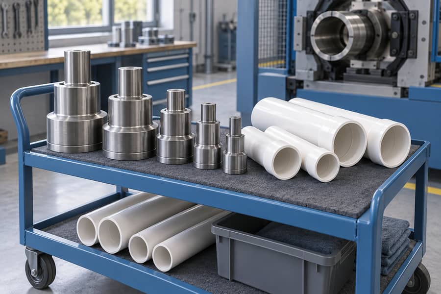
Reducing size changeover time on a belling machine starts with preparing the next job before the current run finishes, using a verified tooling and recipe combination, and controlling the first sockets produced after restart. The useful measure is the time between the last accepted pipe of one size and stable, accepted production of the next size. A shorter mechanical tool exchange alone does not prove that the factory has recovered productive time.
Pipe manufacturers often lose minutes in activities that appear too small to track: finding a clamp insert, confirming a socket drawing, cleaning a cooling connection, waiting for a gauge, or repeating a temperature adjustment. Those delays can accumulate across a shift. A practical improvement program makes each activity visible, removes avoidable waiting, and preserves the checks that protect socket quality.
Define the Changeover You Actually Need to Improve
A diameter change may require a different mandrel, support position, clamp insert, heating arrangement, forming stroke, and cooling recipe. A change between socket profiles can involve additional parts even when pipe diameter stays the same. Wall thickness, pipe length, material formulation, and gasket design may also affect the setup. Treating all of these transitions as one average hides the work that needs attention.
Begin with a transition list. Record the outgoing product and incoming product, including outside diameter, wall specification, pipe length, socket drawing revision, and tooling identification. Group similar transitions together. A small diameter adjustment within one tooling family should be compared with similar jobs, while a change to a different socket system deserves its own baseline.
For a factory evaluating its belling machine configuration, this transition list is also more useful than asking for a general promise of fast setup. It shows which adjustments occur regularly, which parts must be accessible, and which production combinations should be demonstrated during a machine trial.
Measure from Last Good Pipe to Stable Good Production
Define the start and finish points before timing operators. The start is the last accepted pipe from the outgoing order. The finish is reached when the new order has passed the agreed first-piece checks and can continue at its approved operating rate. Record any later hold caused by the changeover separately, so an apparently fast restart does not conceal delayed rejection.
Keep mechanical setup time, thermal stabilization time, trial production time, and quality release time as separate entries. Some tasks overlap, so do not simply add every recorded activity to calculate total downtime. Use a timeline to show the critical path: the sequence of tasks that determines when production can actually restart.
Observe a Complete Changeover Before Buying New Hardware
Follow several representative transitions on the shop floor. Write down what the operator does, what equipment is unavailable, and where waiting occurs. Record the reason for each interruption without turning the observation into a speed competition. Experienced operators often compensate for missing instructions or worn parts; the purpose is to make those hidden dependencies visible.
Classify the work into preparation, removal, installation, adjustment, stabilization, inspection, and release. Also record walking, searching, cleaning, repeated measurement, and corrective adjustment. When a task is repeated, ask what information or physical reference was missing the first time. A second clamp adjustment may indicate an unclear datum rather than insufficient operator skill.
- Tool readiness: Identify missing inserts, fasteners, lifting accessories, hoses, and gauges before the machine stops.
- Adjustment repeatability: Note every position that is found by trial instead of a documented reference.
- Thermal readiness: Record whether the next recipe requires a temperature transition or a different heater arrangement.
- Quality release: Track the time required to cool, measure, identify, and approve the first samples.
Move Preparation Outside the Stopped-Machine Window
The distinction between internal and external setup, explained in single-minute exchange of die, provides a useful organizing principle. An internal setup operation occupies part of the shutdown window because it cannot be performed during production. External work can be completed beforehand without entering a hazardous area or disturbing the running process. The method does not mean every belling changeover should take less than ten minutes.
Build a Complete Kit for the Incoming Product
Prepare the correct mandrel, clamp inserts, guides, stops, seals, fasteners, and approved process sheet together. Include a tooling list with identification numbers and a drawing revision. The person staging the kit should verify compatibility, rather than relying on the next operator to discover mismatched parts during installation.
Store cleaned components in protected locations. Mandrel surfaces and sealing features should not rest against loose tools or abrasive debris. Use suitable lifting and transport equipment for heavy assemblies. An organized cart helps only when it supports the components securely and leaves the operator enough space to handle them safely.
Stage Inspection Equipment at the Same Time
Prepare the gauges and sample identification materials before the machine stops. Confirm that measuring instruments are within their calibration period and suitable for the required tolerance. A gauge that covers the pipe diameter may still be unsuitable for a recessed gasket groove or a tapered socket surface.
Make the incoming inspection plan available beside the recipe. It should specify the features to measure, the conditioning requirement, the sample quantity, and the person authorized to release production. This prevents a finished setup from waiting while somebody searches for acceptance criteria.
Make Mechanical Positions Repeatable
After preparation losses are removed, focus on adjustments that consume the stopped-machine window. Pipe centerline, support height, axial stops, clamp location, and tooling alignment should have clear references. Record settings against a defined datum; a number is unreliable if different operators measure from different surfaces.
Use Positive Location Where the Design Allows It
Locating shoulders, approved stops, and suitable quick-change fixtures can reduce repeated alignment. Their suitability depends on the machine design, process load, tool weight, and required precision. Changes to locking systems, guarding, or load-bearing components should be reviewed by the machine manufacturer before implementation.
Marking a position can be useful, but a painted line cannot correct mechanical play or wear. If a support shifts after tightening, inspect its guide surfaces and fastening arrangement. If a mandrel repeatedly needs correction, verify the mounting interface and alignment rather than storing progressively different offsets in the recipe.
Standardize Connections and Tool Storage
Identify cooling, pneumatic, and electrical connections clearly where applicable. Prevent incorrect connection through approved physical arrangements and documented checks. Do not assume interchangeable fittings prove that two circuits serve the same function. Cooling flow direction, pressure rating, and circuit assignment still matter.
Return removed tooling to a defined condition. Inspect it, record damage, clean it according to the maintenance procedure, and assign a storage location. Deferring all cleaning until the next changeover moves today’s delay into tomorrow’s schedule. A tooling readiness board can distinguish available, under inspection, and unavailable components.
Control Recipes Instead of Recreating Them
A recipe should identify the product and the tooling it was validated with. Depending on the machine, controlled settings may include heating zones, heating duration, pipe rotation, forming motion, pressure or vacuum stages, cooling time, and unloading conditions. Only include parameters that actually exist on the equipment.
Use a naming convention that distinguishes material, outside diameter, wall specification, socket profile, and revision. A file called “160 pipe” is ambiguous if the factory makes several wall classes or connection designs at that diameter. Preserve an approved master and require a recorded reason when a setting changes.
Verify the Selected Recipe Against Installed Parts
Before restart, compare the recipe identifier with the mounted mandrel, inserts, and socket drawing. Where the machine supports tooling identification or recipe permissions, use those features within the approved control design. Otherwise, a clear manual verification can still prevent a wrong combination from entering production.
Recipe storage does not eliminate process validation. Incoming pipe condition, ambient conditions, cooling water, and tooling temperature can change the result. The stored recipe is a controlled starting point with known limits. Operators should record necessary adjustments and obtain approval before replacing the master settings.
Plan the Thermal Transition
Heating and cooling requirements can dominate a changeover even when the mechanical exchange is quick. A different wall thickness or socket length changes how much material must be conditioned. Surface temperature alone does not establish that the pipe wall is ready to form, and the same heater display value does not guarantee the same thermal condition after every restart.
Schedule thermal preparation only in ways permitted by the machine instructions. Do not preheat tooling or alter oven conditions while another job is running unless the equipment and validated procedure support it. The goal is to remove waiting that serves no process purpose, not to shorten a necessary stabilization period.
Record the actual conditions at release, including relevant heater status and cooling supply condition. If a transition repeatedly produces acceptable sockets only after several trials, investigate whether the recipe, stabilization rule, or measurement timing is incomplete. Repeatedly accepting startup scrap as normal prevents the underlying issue from being resolved.
Use a Defined First-Piece Release Sequence
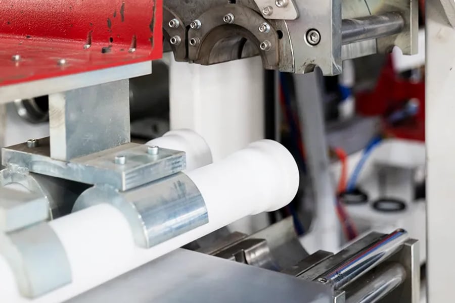
Once tooling and recipe checks are complete, run the approved setup sequence with guards and interlocks functioning. Keep trial pipes identifiable and separate from saleable output until release. A first socket that looks round is not enough evidence that its internal profile, depth, wall distribution, or sealing features are acceptable.
Measure the relevant dimensions after the specified conditioning. For a plain socket, focus on the drawing requirements for diameter, depth, taper, and surface condition. For a gasketed socket, include groove geometry and gasket position where applicable. Use the product’s approved test plan to determine whether assembly or joint testing is required at this stage.
Document the final settings, accepted sample identification, inspection results, and release time. When a trial socket is rejected, identify the likely mechanism before selecting an adjustment. Where the process allows, isolate that adjustment and document what the next measurement shows. Several unrecorded adjustments made together can produce a passing sample while leaving the process difficult to reproduce on the next shift.
Compare Improvements with a Consistent Time Study
The following figures are an illustrative planning example, not measured performance for a Yuyu machine. Assume a factory records a 48-minute changeover from last good pipe to released production. Its non-overlapping critical-path stages are 12 minutes of preparation and searching, 18 minutes of mechanical work, 10 minutes of stabilization, and 8 minutes of inspection and release.
| Critical-path stage | Baseline example | Revised example | Change to validate |
| Preparation and searching | 12 minutes | 3 minutes | Stage and verify the complete incoming kit |
| Mechanical exchange and alignment | 18 minutes | 13 minutes | Use approved locating references and organized connections |
| Thermal stabilization | 10 minutes | 10 minutes | Retain the validated process requirement |
| Inspection and release | 8 minutes | 6 minutes | Prepare gauges and release documents in advance |
In this example, the revised changeover takes 32 minutes and recovers 16 minutes per transition. Four equivalent transitions would recover 64 minutes. That calculation describes available time, not guaranteed extra output: demand, upstream supply, downstream handling, and the operating rate determine whether the recovered time becomes additional accepted pipes.
Track Quality Alongside Changeover Speed
Review median changeover duration as well as the longest events. Record startup rejects, repeated adjustments, first-piece acceptance, and any quality holds discovered after restart. A reduced average can hide a transition that occasionally causes a long interruption. Group the results by product family and transition type before deciding whether an improvement is repeatable.
Discuss results with production, maintenance, and quality personnel together. Maintenance may identify worn locating surfaces; quality may find inconsistent conditioning; production may reveal that the incoming kit arrives after the machine has stopped. Assign each recurring loss to an owner and a verifiable corrective action.
Build the Next Improvement Around Evidence
Start with one frequent transition, create a baseline, and test a limited set of changes. Update the standard procedure only after the new method produces acceptable sockets consistently. Include photographs of approved tool arrangements, clear reference positions, and the first-piece release sequence in operator training. Recheck the method after tooling repairs or control changes.
When requesting equipment modifications or evaluating a new machine, provide the transition matrix, observed delays, pipe samples, and target socket drawings. Yuyu Machinery can use that information as the basis for a changeover and tooling discussion. The most useful target is a repeatable return to accepted production, supported by prepared tooling, controlled settings, and a release process that operators can follow every time.