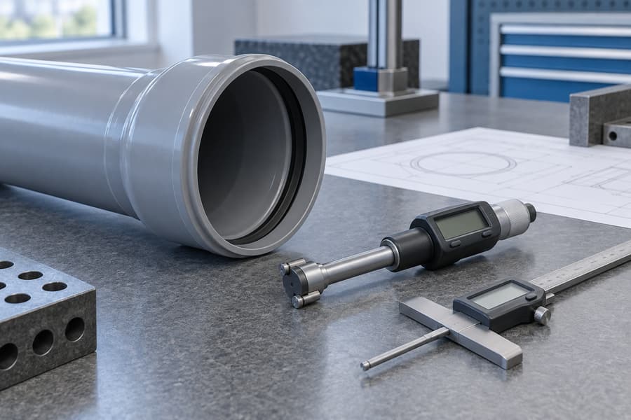
Inspect PVC pipe sockets after belling by checking the cooled socket against its approved drawing, measuring the features that control assembly and sealing, and applying the functional tests required by the pipe specification. Visual appearance is only the first check. A socket can look smooth while its diameter, insertion depth, taper, roundness, wall thickness, or gasket position falls outside the permitted limits.
A useful inspection process links each result to the pipe size, material batch, tooling, machine settings, and inspection time. That record helps distinguish a one-off damaged pipe from a developing process problem. It also gives production personnel evidence for adjusting the process without replacing a defined acceptance requirement with personal judgment.
Start with the Correct Acceptance Documents
Before measuring a socket, identify the product specification and the current socket drawing. Confirm the pipe application, nominal designation, actual outside diameter, wall class, connection type, and any customer requirements. Pressure pipe, drainage pipe, and electrical conduit should not be evaluated against an assumed common socket tolerance.
The drawing or applicable product standard should establish which features are controlled, where they are measured, and the limits that apply. The inspection procedure should then define instruments, conditioning, sampling, and reporting. When those documents disagree or leave a critical dimension unclear, resolve the issue before releasing the batch.
The selected PVC pipe belling machine and its tooling influence repeatability, but a machine specification is not a substitute for the finished pipe acceptance criteria. Inspect the product that will be assembled in service, using the documented requirements for that connection.
Identify the Socket Type
A plain socket for solvent-cement assembly requires attention to its mating dimensions, taper where specified, depth, and surface condition. A socket with a separate sealing ring also requires the correct groove geometry and ring fit. An integrated-gasket socket requires verification that the intended gasket is retained in the correct position and has not been damaged during forming.
Do not use the same gauge or checklist automatically across these designs. A gauge suitable for a straight bore may not evaluate a tapered socket correctly. An assembly test that feels acceptable by hand may fail to reveal a shallow groove, local wall thinning, or an incorrect sealing element.
Condition the Socket Before Final Measurement
Belling changes the pipe end through heating, forming, and cooling. PVC is a thermoplastic material, so temperature and recent thermal history affect dimensions and stiffness. A measurement taken immediately after discharge may be useful for process monitoring, but it should not automatically be treated as the final acceptance measurement.
Use the conditioning time and temperature required by the applicable test method or approved quality procedure. Identify when the sample left the machine and when it was measured. Avoid assigning an arbitrary universal waiting time: pipe wall thickness, socket geometry, cooling conditions, and the referenced method can change what is appropriate.
Support the Sample Without Distorting It
Place the pipe on supports that keep it stable while leaving the socket accessible. Do not clamp a thin socket so tightly that the inspection fixture changes its shape. For large or long pipes, provide sufficient support to prevent bending or rolling during measurement.
Remove loose contamination using an approved method. Avoid scraping, sanding, or otherwise modifying a feature before inspecting it, because that may hide the original condition. If cleaning is necessary to see the surface, document any unusual deposit and determine whether it originated from the pipe, tooling, or handling process.
Perform a Systematic Visual Inspection
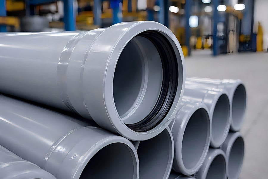
Inspect the complete circumference, including the mouth, internal bore, transition into the pipe body, and sealing features. Use lighting that reveals scratches, folds, uneven surfaces, and localized discoloration. Rotate or reposition the sample so the underside receives the same attention as the most accessible area.
Look for cracks, splits, burns, trapped debris, sharp edges, incomplete forming, obvious eccentricity, and damage from clamps or transfer equipment. Record the location and appearance of a defect rather than immediately assigning a cause. Several different process issues can produce similar visible symptoms.
- Socket mouth: Check the edge profile, visible damage, and any specified chamfer.
- Internal surface: Look for scoring, contamination, folds, and irregular forming marks.
- Transition region: Check for abrupt distortion, cracking, or localized stretching.
- Sealing area: Inspect the groove or installed gasket around the entire circumference.
- Pipe identification: Confirm that the sample can be traced to the correct production order and batch.
A systematic visual pass can immediately reveal damage such as splits, burned areas, and trapped debris. It does not establish pressure capability or leak tightness, and it should not replace dimensional or functional tests required by the product specification.
Measure Socket Diameter at Defined Locations
The internal diameter influences how the mating spigot enters and how the joint functions. Measure at the axial locations specified by the drawing or method, using suitable internal measuring equipment or approved gauges. A single reading at the mouth does not describe the full bore.
For a tapered socket, diameter changes along its length by design. Record the measurement depth together with the result. Comparing readings taken at different depths can create a false impression that the process is unstable. Use a suitable locating stop or purpose-made gauge holder when the measurement procedure requires every reading to be taken at the same axial position.
Choose an Instrument That Fits the Feature
Calipers may be adequate for some accessible checks but may not provide the required contact geometry, reach, or resolution for every socket. Bore gauges, plug gauges, and dedicated fixtures can be more appropriate depending on the tolerance and socket design. Verify that the selected instrument measures the intended feature without damaging the surface.
Check calibration status and inspect contact surfaces before use. Use the required measurement force and follow the instrument procedure. Excessive force can distort a flexible section or produce inconsistent readings. Record the instrument identifier so questionable results can be reviewed if a calibration issue is later discovered.
Check Roundness and Ovality
Measure around the circumference at the specified axial plane. Record the largest and smallest relevant diameters, rather than assuming one horizontal and one vertical reading always capture the extremes. The number and orientation of readings should follow the approved method and be sufficient to identify the shape variation of concern.
A simple dimensional difference is Dmax minus Dmin. If the specification expresses ovality as a percentage, use its defined denominator and measurement location. Different documents can define the percentage differently, so a calculation based on nominal diameter should not be substituted silently for one based on mean diameter.
For a hypothetical example, measured diameters of 110.6 millimeters and 109.8 millimeters have a difference of 0.8 millimeter. That result alone does not establish acceptance. The inspector still needs the applicable limit, the prescribed measurement plane, and confirmation that the sample was conditioned correctly.
Verify Depth, Taper, and Axial Geometry
Measure socket depth from the defined reference surface to the specified internal feature. Distinguish total formed length from usable insertion depth; they may not be the same. A formed shoulder, gasket location, or transition can affect where the mating pipe is intended to stop.
Check that the socket axis and pipe body align within the product requirements. An eccentric or tilted socket can make assembly difficult even when individual diameter readings appear acceptable. If a special fixture is used, confirm its reference surfaces and repeatability before relying on its results.
Inspect the Mouth and Entry Profile
The socket entry should match the drawing and allow the intended assembly procedure. Evaluate any required chamfer, radius, or lead-in feature. Do not add an improvised chamfer merely to make a difficult sample fit; first determine whether the difficulty comes from the socket, spigot, gasket, or assembly method.
Where taper is controlled, inspect it using the specified gauge or measurement method. A socket that is too loose at one location and tight at another may not be adequately described by an average diameter. Preserve the individual readings needed to understand the profile.
Assess Wall Thickness in the Formed Region
Expansion redistributes material at the pipe end, so the original pipe wall measurement does not establish the thickness everywhere in the finished socket. Follow the product requirement for locations and method. Pay particular attention to regions where the geometry changes and where the drawing identifies a minimum thickness.
Depending on the approved procedure, inspection may use a suitable nondestructive instrument or a prepared section from a sample pipe. A nondestructive method must be validated for the material, surface, curvature, and thickness range. Sectioning should preserve the geometry being examined and avoid preparation damage that could be mistaken for a production defect.
Record the position of every reading. An average can conceal a local minimum that matters to acceptance. When thinning is found, retain the relationship between its circumferential position and machine orientation; that information may help production personnel investigate heating or alignment variation.
Inspect Gasket Grooves and Integrated Seals
For a groove intended to receive a separate ring, verify the dimensions specified for width, depth, profile, and axial position. Check the full circumference for incomplete forming and local distortion. Confirm the intended ring identification before an assembly trial, because similar-looking rings can have different cross-sections or applications.
For an integrated seal, inspect seating, orientation, cleanliness, and visible damage without disturbing the retained gasket. A seal should not be removed simply to inspect the groove unless the approved destructive test method calls for that action. Keep inspected or sectioned samples out of normal saleable production.
The general function of a gasket is to seal between mating surfaces, but actual joint performance depends on the complete design. Correct socket geometry, spigot condition, seal material, and assembly procedure must work together. An installed gasket does not by itself prove a leak-tight or axially restrained joint.
Use Assembly and Joint Tests for Their Intended Purpose
A controlled fit check can reveal difficult insertion, poor alignment, or a displaced seal. Use a mating component that conforms to the specified dimensions, and follow the approved preparation, lubrication, insertion, and inspection steps. Record any force measurement only when the method and equipment are defined.
Where the product specification requires pressure, vacuum, leakage, or other joint performance testing, use that procedure and its acceptance criteria. A quick shop-floor fit check cannot replace it. Pressure testing should be performed with suitable equipment and controls by trained personnel under the established test procedure.
Keep dimensional acceptance and functional acceptance as separate records. A passing sample test does not automatically release every pipe in a batch, while one dimensional measurement cannot represent all service conditions. The sampling plan determines how individual results support a production decision.
Create an Inspection Record That Supports Action
| Record field | What to capture | Why it matters |
| Product identity | Order, material batch, size, wall class, and socket drawing revision | Connects the result to the correct requirement |
| Process identity | Machine, tooling, recipe, production time, and operator | Supports investigation of recurring variation |
| Conditioning | Discharge time, measurement time, and required environmental condition | Makes results comparable |
| Measurements | Feature location, readings, limits, and instrument identification | Shows the actual basis for acceptance |
| Disposition | Accepted, held, rejected, or approved rework decision | Prevents unapproved product from entering shipment |
Use photographs when they help locate a defect, but do not replace numerical records with images alone. A photograph may show a crack clearly while revealing little about an internal diameter or a groove depth. Keep sample identification visible in the inspection record without obscuring the feature being documented.
Respond to Nonconforming Results Before Adjusting Blindly
Identify and segregate affected production according to the factory’s quality procedure. Determine the last verified acceptable point and review the interval since that check. Confirm the instrument, measurement location, conditioning, and drawing revision before changing machine settings in response to an unexpected result.
Then investigate the relevant process evidence: incoming pipe dimensions, heating condition, tooling identity and wear, alignment, forming sequence, cooling supply, and handling damage. Change only justified variables and verify the effect through another controlled inspection. Record both the adjustment and the result so the same issue can be recognized later.
Review inspection frequency after startup, size changeover, tooling maintenance, and process interruptions using the approved control plan. The objective is to detect drift early enough to contain the affected product. Yuyu Machinery can discuss tooling and process requirements when provided with socket drawings, samples, and inspection records through the technical support contact. Clear evidence makes that discussion more productive than a description that the socket simply looks wrong.