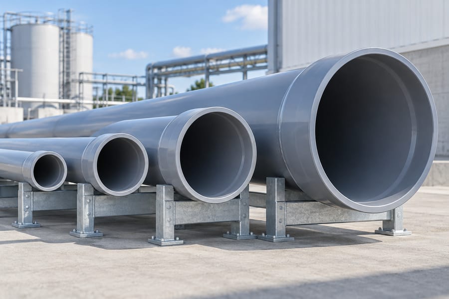
Choose a PVC pipe belling machine by matching its validated working range to your actual pipe outside diameters, wall specifications, socket designs, cut lengths, and required output. The smallest and largest diameter in a brochure are only the starting boundaries. A suitable machine must form acceptable sockets across the product combinations your factory will run, with compatible tooling, stable handling, and enough capacity for the production schedule.
This makes diameter selection a product-matrix exercise rather than a search for the widest available range. A factory producing short conduit pipes has different feeding and output requirements from one making long, thick-wall pressure pipes. Even two factories using the same nominal diameter can need different heating arrangements, socket tooling, and inspection plans.
Translate Nominal Sizes into Actual Manufacturing Dimensions
Start by listing the actual outside diameter for every product. Nominal size labels are convenient for sales and project specifications, but their relationship to measured dimensions depends on the pipe system. Do not assume a nominal designation from one market is interchangeable with an apparently similar designation from another.
Record the applicable dimensional standard and drawing revision beside each size. Include the permitted incoming pipe variation, because tooling and clamping must accommodate conforming production without damaging or misaligning the pipe. If your factory supplies several markets, identify which products share physical dimensions and which only share a nominal label.
Use this information when reviewing Yuyu Machinery’s PVC pipe belling equipment. Ask for written confirmation of each required combination, rather than interpreting a broad diameter range as approval for every wall class and socket profile inside it.
Include Pipe Length and Straightness
Cut length affects the frequency of arriving pipes and the physical support arrangement. Short pipes may need different transfer and positioning provisions from long pipes. Long products require enough support to maintain alignment between the pipe body, clamp, heating station, and forming tool.
Document relevant incoming straightness and end-condition requirements. A machine cannot reliably compensate for every upstream variation through clamp force or recipe changes. The equipment discussion should establish what pipe condition the beller expects at its inlet and how nonconforming incoming pieces are handled.
Add Wall Thickness to Every Diameter Entry
Outside diameter does not describe the amount of material that must be heated and reshaped. Two PVC products may share an outside dimension while differing substantially in wall section; their resistance to deformation and response to heating must therefore be assessed separately. A configuration demonstrated on a thin wall should not automatically be accepted for the thickest product at that size.
Specify the actual wall range and the relevant pressure class or dimensional designation. Where a ratio such as SDR is used, still provide the dimensional requirement needed for the machine and tooling review. Include the pipe formulation and material grade when these affect the validated process.
Evaluate Both Thermal and Mechanical Demands
Thicker walls may require different heating exposure and cooling conditions to establish a stable socket profile. Thin walls may be more sensitive to local deformation during clamping and transfer. Neither situation is resolved by choosing a machine solely because its maximum diameter exceeds the pipe size.
Ask how the proposed equipment controls the process for your product matrix. Relevant questions include the available heating arrangement, support and clamp design, forming method, cooling provision, and recipe control. The answer should describe the offered configuration, not optional features that are absent from the quotation.
Match the Socket Design Before Selecting Tooling
The connection drawing determines what the machine must create at the pipe end. Plain sockets, ring-seal sockets, and integrated-gasket sockets have different forming and verification requirements. Socket length, taper, groove profile, and insertion geometry can change the tooling even when outside diameter remains constant.
Provide the finished socket drawing with dimensions, tolerances, and the intended mating component. Where a gasket is involved, include its approved specification and sample requirements. A ring that fits the nominal pipe size is not necessarily compatible with the selected groove or forming process.
Separate Machine Range from Tooling Coverage
A machine platform may cover many pipe diameters while an individual mandrel or insert set covers only a specific size and profile. Confirm which tooling sets are included, which are additional, and which product combinations require a different configuration. Request identification and compatibility records for the delivered tools.
A useful tooling schedule lists the pipe product, mandrel, clamp inserts, support adjustments, socket profile, and approved recipe. It should also identify items shared between products. This makes the actual scope of supply visible and prevents the assumption that one machine automatically arrives ready for every diameter in its range.
Test the Smallest Diameter for Handling and Output
The smallest diameter is not always the easiest product to process. A small pipe can be lightweight, flexible, and produced at a high linear speed. When it is cut into short lengths, the beller may need to accept and discharge pipes very frequently. Feeding, spacing, alignment, and unloading can become more demanding than the forming motion itself.
Calculate the arrival interval from line speed and cut length. At an illustrative speed of 18 meters per minute and a cut length of 3 meters, a single stream produces 6 pipes per minute, or one every 10 seconds. These assumed values demonstrate the calculation; they do not describe a specific Yuyu production line.
Confirm the Actual Batch Arrangement
If the proposed machine processes multiple small pipes together, verify how they are collected, positioned, heated, formed, and discharged. Ask what happens when one pipe is missing, misaligned, or outside the incoming specification. The quoted number of pipes per cycle must correspond to completed acceptable pieces in the supplied configuration.
Observe a repeated run using the intended pipe length. A brief demonstration with manually arranged pipes does not establish automatic inlet performance. Where manual loading is part of the design, include the real handling requirement in the production assessment.
Test the Largest Diameter for Support and Process Stability
At the upper end of the range, review pipe mass, tool mass, access, and alignment as well as the nominal opening of the machine. Supports must carry the product through the actual sequence without excessive sagging or rolling. Clamping should locate the pipe reliably while preserving its condition.
Heating and cooling must produce acceptable dimensions throughout the required socket geometry. Ask for samples that have undergone the specified conditioning before final inspection. A large socket that looks correct immediately after forming may still need dimensional verification after its thermal condition stabilizes.
Look Beyond Maximum Diameter Alone
The most demanding trial may combine the largest outside diameter with the thickest wall and the longest socket. Another critical case may be a thinner wall with demanding roundness limits. Identify these combinations from the product requirements instead of assuming there is one universal worst case.
Confirm that the offered machine has the utilities and handling accessories required for those trials. The results should not depend on temporary support arrangements or additional cooling equipment that will not be supplied or available at the factory.
Build a Diameter-and-Application Selection Matrix
A selection matrix keeps the decision tied to production needs. Include all current products, then identify planned products separately with their expected volumes and introduction dates. Distinguish firm requirements from possibilities so an uncertain expansion does not dominate the equipment choice.
| Product group | Information to define | Machine capability to verify |
| Small, short pipes | Outside diameter, cut length, line speed, and socket profile | Frequent feeding, positioning, and completed output |
| Routine production sizes | Order volume, wall range, tooling, and normal running schedule | Sustained accepted output and repeatable setup |
| Large or heavy pipes | Mass, length, wall thickness, and support requirements | Handling stability, heating, forming, and cooling |
| Integrated-gasket products | Socket drawing, seal specification, and inspection plan | Compatible seal loading and controlled forming sequence |
| Future products | Confirmed dimensions, expected volume, and launch timing | Documented upgrade or tooling path |
The matrix does not replace a technical specification. Its purpose is to reveal gaps and guide the detailed review. If one product lies outside the demonstrated configuration, mark that gap explicitly and resolve it through testing, a different machine arrangement, or a revised production plan.
Compare One Wide-Range Machine with Separate Production Groups
A wide working range can simplify equipment allocation, but it may also require more tooling and frequent adjustments. Separate machines for distinct product groups may improve scheduling or reduce repeated transitions, although they require additional space, utilities, and operating resources. The better arrangement depends on the actual workload.
Compare both options using annual or weekly order patterns, setup frequency, available shifts, and expected downtime. Count how often the factory moves between distant sizes and incompatible socket designs. A rarely used extreme diameter should not be treated as if it has the same production weight as the size that runs every day.
Evaluate Flexibility Through Real Transitions
Request a representative size change during the equipment evaluation. Measure from the last accepted pipe of the outgoing product to approved production of the incoming product. Include tool handling, support adjustment, recipe selection, stabilization, and first-piece inspection.
Ask which settings are stored, which positions have physical references, and which tasks remain manual. A touchscreen recipe does not necessarily reposition clamps, guides, or supports. The demonstration should show the actual responsibilities of the operator and the tools needed to complete them.
Confirm Capacity for Each Important Size
For one extrusion stream, required pipes per hour equal 60 multiplied by line speed in meters per minute and divided by cut length in meters. Compare that requirement with demonstrated completed output for the same diameter, wall, and socket. Do not apply the best small-pipe cycle time to the entire range.
For machines with overlapping stations, distinguish the time one pipe spends in the system from the interval between completed pipes. For machines processing several pipes together, confirm the completed batch size. Include handling and quality losses when estimating accepted output over a shift.
Short interruptions also matter. An inline layout may need buffering and enough recovery capacity to clear a temporary queue. An offline layout needs storage and scheduling that accommodate incoming orders. Review the complete production flow instead of treating the beller as an isolated machine.
Check Factory Utilities, Access, and Maintenance
Confirm the electrical supply, compressed-air requirements, cooling-water conditions, and any vacuum requirements for the offered configuration. Ask for the specified values and connection details in the technical documentation. Utility demand should be assessed under the relevant operating condition, not inferred from pipe diameter alone.
Review floor space with the longest pipe, maintenance access, tool changes, and material flow included. Leave enough room for safe handling of heavy mandrels and access to service points. A machine footprint drawing without loading and maintenance space can understate the area the installation needs.
Discuss wear parts and inspection of tooling surfaces, seals, heaters, and cooling circuits as applicable. Clarify the availability of drawings, operating instructions, spare-part identification, and support for additional tooling. These provisions influence how reliably the factory can maintain its approved diameter range over time.
Check the Inspection Tools Included with Each Size
Ask whether the delivery includes inspection gauges or only forming tools. These serve different purposes. A mandrel shapes the socket, while a qualified gauge verifies a specified feature after forming and conditioning. Establish who will supply the gauges, which drawing revision they follow, and how they will be calibrated. For a broad diameter range, plan storage and identification so the correct gauge is available during every first-piece release. Include the inspection method in operator training; otherwise, a fast mechanical size change may still leave production waiting for a reliable acceptance decision.
Require a Trial and Acceptance Plan Tied to Your Matrix
Select trial products that represent the main production volume and the critical range boundaries. Agree on incoming pipe condition, tooling, settings, utilities, output measurement, and finished socket acceptance. Keep the material formulation consistent with the intended production where practical.
Measure dimensions after the required conditioning and perform the functional tests specified for the connection. The trial record should identify which product combinations were actually demonstrated and which remain subject to validation. Avoid converting a successful test on one diameter into an unsupported claim about every other size.
The material behavior of PVC provides useful background, but final selection depends on the specific pipe and process. Provide Yuyu Machinery with your completed diameter matrix and socket drawings through the equipment inquiry page. A documented match between products, tooling, capacity, and acceptance requirements is the clearest basis for choosing a machine that fits your factory’s diameter range.