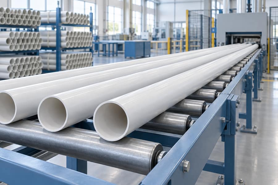
Calculate the required belling machine capacity by converting extrusion speed into the number of cut pipes arriving per hour, then comparing that demand with the machine’s sustainable output for the same pipe and socket specification. For one extrusion stream producing one bell on each pipe, the basic arrival rate is line speed divided by cut length. The complete selection must also account for parallel streams, machine cycle structure, interruptions, rejects, and the space available to buffer pipes.
A machine that appears fast enough in a product table can still restrict an extrusion line. The quoted figure may apply to a smaller diameter, a different wall thickness, a different socket profile, or several pipes processed together. A useful calculation therefore begins with a defined product and ends with a documented production trial, rather than stopping at the highest advertised output.
Collect the Inputs in Consistent Units
Prepare a worksheet for each important product. Record material, actual outside diameter, wall specification, cut length, socket drawing, number of ends to be belled, and the intended extrusion speed. Include both routine running conditions and the highest sustained rate the factory expects to use. A short peak during a test is different from a stable production requirement.
Keep length units consistent. If speed is expressed in meters per minute, cut length must be in meters. If output is supplied in kilograms per hour, convert it using the actual mass per meter of the relevant pipe. A mass output figure by itself does not tell you how often a finished pipe reaches the belling station.
When discussing a pipe belling machine, provide the product worksheet with the inquiry. It allows the equipment configuration to be assessed against actual pipe arrivals and socket requirements instead of a single general speed target.
Define the Production Boundary
State whether the beller serves one extrusion stream, several parallel streams, or stored pipes from multiple lines. Clarify whether it receives every cut pipe or only selected orders. Also define the output being counted: pipes per hour, sockets per hour, or batches per hour. These quantities are equal only in specific arrangements.
If every pipe needs two belled ends, socket demand is twice the pipe arrival rate. That does not automatically mean the installed equipment must run twice as fast: a machine may process both ends in one coordinated operation, or the production layout may use separate stations. The calculation must represent the actual handling and forming sequence.
Convert Extrusion Speed into Pipe Arrivals
For a single stream, let v be extrusion speed in meters per minute and L be cut length in meters. The arrival rate in pipes per minute is v divided by L. Multiplying by 60 converts that result into pipes per hour. The interval between arriving pipes is 60 multiplied by L and divided by v, expressed in seconds.
- Pipe arrival rate: R = 60 × v ÷ L, in pipes per hour.
- Arrival interval: T = 60 × L ÷ v, in seconds per pipe.
- Multiple identical streams: Total arrival rate = number of streams × R.
- Different streams: Calculate each stream separately and add the resulting arrival rates.
As an illustrative example, a line running at 12 meters per minute and cutting 6-meter pipes produces 2 pipes per minute, or 120 pipes per hour. One pipe arrives every 30 seconds. If the same line cuts 3-meter pipes without changing linear speed, demand doubles to 240 pipes per hour and the interval falls to 15 seconds.
This is why pipe length belongs in every capacity discussion. A beller qualified on long pipes may be unable to accept the same extrusion speed when the factory switches to shorter products, even though diameter, wall thickness, and material remain unchanged.
When Only Mass Output Is Available
Let M be extrusion output in kilograms per hour and m be actual pipe mass in kilograms per meter. The corresponding linear output is M divided by m, in meters per hour. Divide that result by cut length to obtain pipes per hour. Use the measured or approved product mass, including the relevant material formulation and dimensions.
For example, an assumed output of 600 kilograms per hour, a pipe mass of 2 kilograms per meter, and a cut length of 6 meters give 50 pipes per hour. These are hypothetical inputs for demonstrating the formula. They are not a rating for any particular material, extrusion line, or Yuyu machine.

Understand What the Belling Cycle Figure Means
A complete pipe may spend time loading, heating, transferring, forming, cooling, and unloading. In a machine that performs those activities sequentially on one pipe, their durations contribute to the total cycle. In a machine with overlapping stations, several pipes may be at different stages simultaneously. The elapsed time for one pipe to travel through the machine is then different from the interval between finished pipes.
Sequential Single-Pipe Operation
For a machine producing one completed pipe every t seconds, theoretical capacity is 3,600 divided by t. A measured cycle of 30 seconds corresponds to 120 pipes per hour before allowing for interruptions and rejected output. Confirm that the cycle includes the necessary transfer and handling time, not just mandrel movement.
Do not shorten the assumed heating or cooling duration simply to make the arithmetic match the extrusion line. Those stages must produce an acceptable socket. The valid cycle time is the one demonstrated with the specified pipe and the approved quality checks.
Overlapping Stations and Multiple Pipes per Batch
For a system discharging n completed pipes every t seconds at steady state, theoretical capacity is 3,600 × n ÷ t. The batch size must represent pipes actually completed together. Counting heating positions as finished pipes, or multiplying by the number of stations when each station performs a different step, overstates capacity.
A hypothetical machine releasing four pipes every 40 seconds has a theoretical output of 360 pipes per hour. Each individual pipe could spend longer than 40 seconds inside the machine because heating and forming overlap. Request a timing diagram or observe repeated discharge events to establish the real steady-state output interval.
Separate Instantaneous Capacity from Shift Output
Instantaneous capacity describes how fast the machine runs while producing. Shift output also includes downtime, reduced-speed periods, and quality losses. The concept of overall equipment effectiveness helps separate these influences, provided the factory uses consistent definitions and does not count the same loss twice.
For an initial planning estimate, accepted output can be expressed as theoretical output multiplied by availability, performance, and quality factors. Availability represents the share of planned production time the machine runs. Performance represents its running rate relative to the selected reference rate. Quality represents accepted output divided by total output.
If the cycle time used in the calculation already comes from sustained actual running, some speed losses may already be included. Applying another performance reduction for those same losses would understate capacity. Similarly, if planned changeovers have already been removed from available production hours, do not subtract them again through a second availability allowance.
An Illustrative Effective-Capacity Calculation
Assume theoretical capacity is 180 pipes per hour, availability is 90%, performance is 95%, and first-pass acceptance is 99%. Estimated accepted output is 180 × 0.90 × 0.95 × 0.99, or approximately 152 pipes per planned hour. These assumptions are a teaching example and must be replaced with measured factory data.
Against a requirement of 120 accepted pipes per hour, that example has roughly 32 pipes per hour of estimated output margin. However, an inline system must also accept incoming pipes during individual disturbances. A favorable hourly average does not prove that the conveyor can absorb a two-minute stop.
Calculate Buffer Requirements for Short Interruptions
A buffer temporarily separates the continuous extrusion stream from intermittent belling. If the beller stops for d minutes while pipes keep arriving at r pipes per minute, the buffer needs room for at least r × d additional pipes, before allowing for pipes already waiting and practical handling limits.
At 2 incoming pipes per minute, a two-minute interruption adds four pipes. That arithmetic is simple, but the physical arrangement must accommodate pipe length, diameter, rolling behavior, support requirements, and safe transfer. Four large pipes may require a very different storage arrangement from four small conduit pipes.
Check Whether the Machine Can Clear the Queue
After restart, the running belling rate must exceed the arrival rate if the queue is to shrink. If the beller processes 3 pipes per minute while 2 continue arriving, the net recovery rate is 1 pipe per minute. Clearing the four-pipe backlog therefore takes four minutes, assuming no further interruptions or transfer restrictions.
A buffer cannot solve a permanent capacity shortfall. If the belling rate equals or falls below the arrival rate during normal operation, the stored quantity will not recover after disturbances. The factory must change the configuration, use additional capacity, adjust its production schedule, or reduce the upstream rate within an approved operating plan.
Evaluate the Product Mix, Not Only One Favorable Size
Build a capacity matrix covering the combinations most likely to challenge the equipment. Small, short pipes can create the highest arrival frequency. Thick walls or long sockets can require longer thermal treatment. Large diameters can increase handling and support demands. A particular gasket-loading sequence can add a separate constraint.
| Product condition | Capacity question | Evidence to request |
| Shortest cut length | Can feeding and discharge keep pace with frequent arrivals? | Sustained transfer and output timing |
| Thickest approved wall | Can heating and cooling meet the required output? | Accepted sockets at the demonstrated cycle |
| Largest pipe diameter | Can supports, clamps, and handling maintain alignment? | Full-size production trial |
| Gasketed socket | Does ring loading or verification limit the cycle? | Complete repeated sequence with the intended gasket |
| Frequent size changes | Does the shift retain enough available production time? | Last-good to stable-good changeover records |
For each product, calculate demand and demonstrated output using the same units. Then apply the expected order quantities and available hours. A machine can be fast enough for every individual product yet still miss the weekly schedule when changeovers and short orders consume too much time.
Allow for Startup, Changeovers, and Offline Work
Inline capacity analysis focuses on continuous acceptance of the extrusion flow. Offline analysis also needs a workload calculation. Multiply the planned quantity of each product by its demonstrated processing time, add the required setup and release periods, and compare the total with the hours actually available.
If two extrusion lines feed one offline beller, include overlapping schedules and storage limits. An average weekly workload below available hours can still produce an unmanageable queue when several large orders arrive together. Review the timing of releases, handling labor, and access to compatible tooling.
Startup qualification also consumes real capacity. Keep trial pipes and rejected sockets separate from accepted output in the production record. If the planning model assumes immediate full-speed production after every changeover, compare that assumption with the factory’s actual first-piece release history.
Verify the Calculation During a Representative Trial
Agree on the trial conditions before testing: pipe material, dimensions, wall specification, length, socket drawing, utilities, tooling, and acceptance criteria. Record the duration and distinguish warmup from stable production. Count completed pipes, accepted pipes, interruptions, and any operator intervention required to keep the sequence running.
Observe the inlet and outlet as well as the forming station. A fast forming cycle may be offset by a slow transfer device, inconsistent pipe spacing, manual unloading, or a downstream stacker. Include those constraints in the agreed system boundary rather than assigning all losses to the belling mechanism.
After the sockets have undergone the required conditioning, confirm dimensional and functional acceptance under the approved inspection plan. Capacity demonstrated with unacceptable sockets is not usable production capacity. Preserve the trial records with the recipe and tooling identifiers so the factory can reproduce the result after installation.
Turn the Worksheet into a Clear Equipment Requirement
A useful specification states the required accepted pipes per hour for each critical product, the incoming pipe interval, the permitted accumulation, and the expected recovery from a defined interruption. It also identifies changeover frequency and the inspection basis. This makes competing configurations easier to assess without relying on a single headline speed.
Send Yuyu Machinery the product matrix, extrusion speed, cut length, socket drawings, and available layout through the technical inquiry page. The resulting discussion can focus on heating positions, forming capacity, pipe handling, and buffer arrangements that fit the actual production requirement. Revisit the calculation whenever pipe length, material, socket geometry, or the production schedule changes.