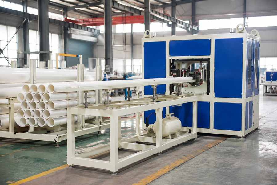
Pipe diameter changes the geometry and load conditions of the complete perforating process. As diameter increases, the working centerline rises, the clamping range expands, tool-head travel becomes longer, rotary drive demand increases, and the support and feeding system requires more space.
Configuration Changes Across Pipe Diameters
Different diameter ranges create noticeably different layouts for a pipe perforating machine. The following groups provide a practical overview, although the final configuration also depends on wall thickness, hole pattern, perforating method, and production speed.
| Plastic Pipe Diameter Range | Typical Machine Configuration Impact |
| Small diameter: 20–110 mm | Compact clamps, smaller rollers, shorter tool travel, faster indexing, and lighter feeding equipment |
| Medium diameter: 110–315 mm | Adjustable supports, wider clamps, extended tool positioning, and a stronger rotary system |
| Large diameter: 315–630 mm+ | Heavy-duty frame, large-opening clamps, higher-torque drive, longer tool travel, and wider feeding equipment |
The difference between these diameter groups affects more than the available machine opening. It changes how the plastic pipe is centered, held, rotated, reached by the cutting tool, and transferred through the production line.
How Pipe Diameter Affects Key Machine Configurations
As diameter increases, the plastic pipe occupies a higher and wider position inside the machine. As pipe diameter increases, the outer wall sits farther from the rotational center, while circumference and turning resistance also rise.
The required machine range should therefore be determined from both the smallest and largest planned pipe sizes. The following five areas show how diameter changes specific parts of a Pipe Perforating Machine.
Raises the Working Centerline
Pipe radius determines the distance between the center of the plastic pipe and its outside surface. When the support reference remains unchanged, a larger diameter raises the pipe centerline and changes the working height of the clamps, cutting head, rollers, and feeding conveyor.
For example, a 110 mm pipe has a radius of 55 mm, while a 630 mm pipe has a radius of 315 mm. The 260 mm difference must be accommodated by the machine structure or its adjustable positioning system.
| Pipe Diameter | Radius | Difference from 110 mm Pipe |
| 110 mm | 55 mm | 0 mm |
| 315 mm | 157.5 mm | 102.5 mm |
| 500 mm | 250 mm | 195 mm |
| 630 mm | 315 mm | 260 mm |
This vertical change affects the complete pipe path rather than only the perforating station. The feeding center, support center, rotary center, and tool position must remain aligned throughout production.
Main configurations affected include:
- Cutting-head installation height
- Clamp and rotary-center position
- Support-roller level
- Feeding-conveyor alignment
- Internal support position
A fixed working centerline is practical for one stable diameter. Equipment covering a broader size range may need adjustable rollers, movable heads, or lifting supports to maintain the correct center.
Expands the Clamping Range
The smallest and largest pipe diameters determine the required clamp opening, jaw travel, and frame width. A machine covering 20–110 mm pipes spans 90 mm in diameter, while a 110–630 mm range spans 520 mm.
Surface curvature also changes with diameter. Small pipes require more curved inserts for stable contact, whereas large pipes need wider contact surfaces and a stronger clamp structure to resist movement during perforating.
Important clamping changes include:
- Greater jaw opening and travel
- Wider clamp-frame dimensions
- Different insert curvature
- Larger contact surfaces
- Increased structural rigidity
A universal clamp may cover several nearby diameters, but a very broad range usually requires replaceable inserts or adjustable contact blocks. One fixed jaw profile is unlikely to hold both a 50 mm pipe and a 500 mm pipe with the same stability.
| Diameter Range | Typical Clamping Configuration |
| 20–75 mm | Compact jaws with tightly curved inserts |
| 75–250 mm | Adjustable jaws with replaceable contact blocks |
| 250–400 mm | Wider clamps with broader support surfaces |
| 400–630 mm+ | Reinforced clamps with a large opening range |
These ranges illustrate configuration differences rather than fixed design standards. Wall thickness still influences the required pressure because a large thin-wall pipe may deform more easily than a smaller thick-wall pipe.
Extends Tool-Head Travel
Diameter changes the radial position of the outside pipe surface. A 100 mm pipe has a radius of 50 mm, while a 500 mm pipe has a radius of 250 mm, creating a 200 mm difference in the required cutting-head position.
Longer axis travel increases machine flexibility but may also add non-cutting movement. Stored starting positions allow the cutting head to approach from a location matched to each pipe diameter.
Tool-head travel may include:
- Diameter-position adjustment
- Rapid approach distance
- Controlled cutting feed
- Tool penetration depth
- Return stroke
- Tool-change clearance
The required movement also depends on the perforating method. Drilling and milling need controlled feed through the pipe wall, while punching requires enough stroke for the punch, die clearance, and waste release.
Increases Rotary Drive Demand
Larger diameters increase pipe circumference and the surface distance travelled during each indexing movement. They may also increase pipe mass and rotational inertia, particularly when greater diameter is combined with a thicker wall or longer pipe length.
For a six-hole pattern, the pipe rotates 60° between holes regardless of diameter. However, the surface of a 630 mm pipe travels much farther during that movement than the surface of a 100 mm pipe.
The rotary configuration may require:
- Higher motor and gearbox torque
- Controlled acceleration and deceleration
- Stronger braking capacity
- More rigid locking
- Larger drive rollers or chucks
- Greater support capacity
The rotary drive must reach each programmed angle without slipping, overshooting, or drifting after stopping. Larger pipes generally place greater demand on the drive and locking mechanism, while small pipes may slip when acceleration is too aggressive.
| Pipe Diameter | Approximate Circumference | Surface Travel per 60° Index |
| 100 mm | 314 mm | 52 mm |
| 200 mm | 628 mm | 105 mm |
| 315 mm | 990 mm | 165 mm |
| 500 mm | 1,571 mm | 262 mm |
| 630 mm | 1,979 mm | 330 mm |
These values are calculated from pipe geometry, but the required motor capacity cannot be selected from diameter alone. Pipe weight, length, roller contact, acceleration, and hole quantity must also be included.
Enlarges Support and Feeding Space
Diameter determines the width and height required for loading racks, guide rails, support rollers, conveyors, separators, and discharge areas. Small pipes can use compact channels, while large pipes require wider passages, stronger frames, and greater vertical clearance.
The feeding structure must accommodate the maximum diameter without losing control of smaller products. Pipe length and weight also affect roller quantity, transfer-motor capacity, support spacing, and the overall line footprint.
Main feeding and support changes include:
- Wider guide-rail adjustment
- Greater roller width and load capacity
- Increased vertical and lateral clearance
- Additional support points for long pipes
- Stronger transfer drives
- Wider loading and discharge areas
A feeding line designed mainly for large pipes may leave too much free space around smaller diameters. Adjustable guides, movable rollers, or replaceable inserts help prevent small pipes from rolling sideways or entering below the correct perforating center.
Wide-Range or Dedicated Configuration?
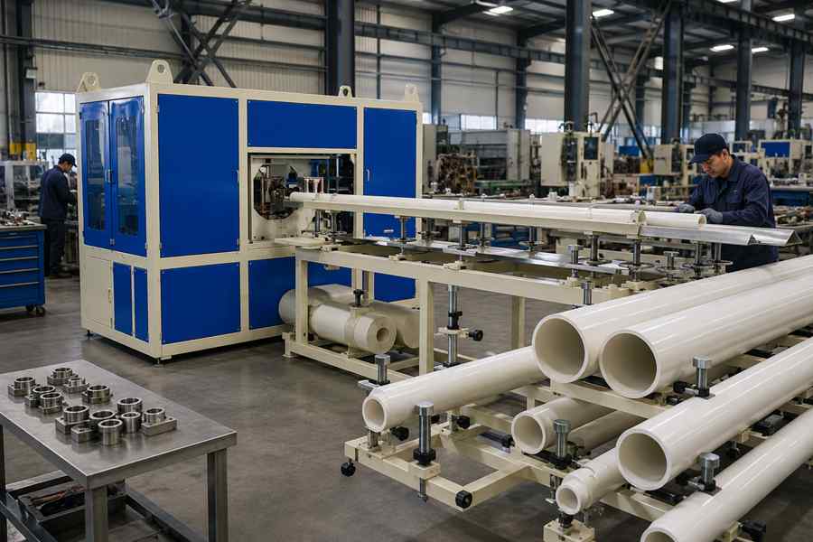
A wide-range perforating machine is useful when several plastic pipe diameters appear regularly in production. It may include adjustable supports, movable cutting heads, interchangeable clamps, servo indexing, and stored diameter recipes.
However, a 20–630 mm range is mechanically more demanding than a 110–315 mm range. The wider range requires longer travel, larger openings, more tooling changes, and greater flexibility in feeding and centering.
| Production Requirement | Suitable Machine Configuration |
| One stable pipe diameter | Fixed centerline and dedicated tooling |
| Several nearby diameters | Adjustable clamps and shared supports |
| Frequent diameter changes | Servo positioning and stored recipes |
| Very wide diameter range | Modular tooling and movable components |
| High-volume fixed orders | Diameter-specific feeding and clamping |
A wider advertised range does not automatically improve production performance. When most orders use a limited diameter range, an oversized configuration may add unnecessary tool travel, setup work, and mechanical complexity.
A narrower machine can provide shorter positioning movement, simpler feeding, faster changeover, and more stable centering. The correct choice should reflect the actual order mix rather than the largest possible pipe.
Key Requirements for Machine Configuration and Evaluation
Buyers should provide complete plastic pipe data before the machine is configured. Outside diameter is the starting point, but it does not fully determine the required frame, cutting system, rotary drive, or support capacity.
Important production information includes:
- Minimum and maximum outside diameter
- Wall thickness for each size
- Pipe length and weight
- Hole diameter and shape
- Number of holes per row
- Angular and longitudinal spacing
- Perforating method
- Required production speed
The smallest and largest planned pipes should both be included in the machine trial. Testing only a medium diameter cannot confirm whether the equipment can center a small pipe or rotate a large pipe reliably.
Buyers should also inspect a complete diameter changeover. Clamp replacement, roller positioning, cutting-head adjustment, guide-width changes, and recipe loading should all be included in the evaluation.