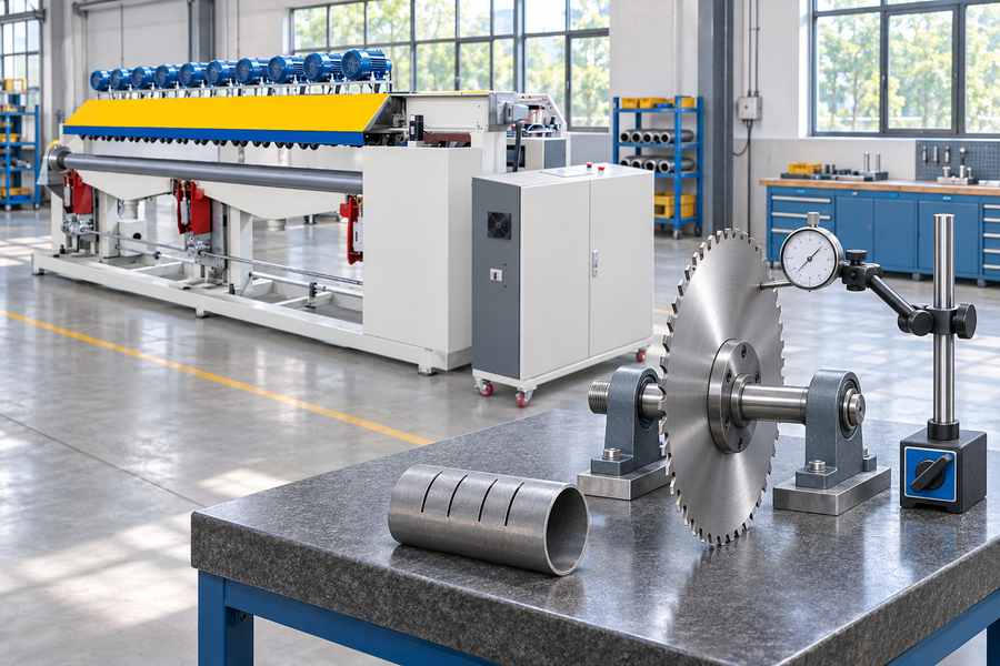
Spindle and blade runout are distinct sources of rotational variation in a pipe slotting machine, but neither alone determines finished slot width.
Reliable diagnosis separates spindle, mounting-interface, and blade checks, then verifies results through controlled cutting trials and defined slot-width inspection under representative pipe and feed conditions for the intended application.
Understanding Spindle Runout and Blade Runout
Spindle runout and blade runout describe different types of geometric variation within a pipe slotting machine’s rotating assembly. Understanding their measurement references is essential before evaluating their effects on cutting accuracy.
Spindle Radial Runout and Axial Runout
Spindle runout refers to the variation in the measured position of a spindle during rotation. Total indicator reading (TIR) represents the difference between the maximum and minimum indicator readings over one complete revolution.
Radial runout describes movement perpendicular to the spindle’s rotational axis. It is commonly checked against a suitable cylindrical reference surface near the spindle nose or another specified measurement location.
When radial runout exists, the spindle reference surface does not maintain a perfectly constant position relative to the measuring instrument. The measured variation may reflect shaft geometry, bearing condition, or other mechanical influences.
Axial face runout describes variation in the position of a reference face along the spindle axis during rotation. An indicator contacts the selected face while the spindle turns, recording its maximum and minimum readings.
The measurement radius matters because face geometry can produce different readings at different distances from the rotational axis. Therefore, an axial face-runout result should always identify its reference face and indicator contact radius.
Axial endplay is a separate measurement. It describes axial displacement when an appropriate force is applied to the spindle, rather than rotational variation observed during one revolution.
A spindle can exhibit face runout, axial endplay, or both. These conditions require separate measurements because they represent different mechanical behaviors and may influence cutting stability differently.
Bearing condition, shaft geometry, mounting interfaces, and mechanical wear can contribute to spindle-related variation. However, a measured TIR value alone does not identify which component requires attention.
Flange Seating and Blade Runout
The flange provides a mounting interface between the spindle and cutting blade where this arrangement is used. Its contact surfaces influence how consistently the blade sits relative to the rotational axis.
Flange face runout describes variation measured against the flange’s reference face during rotation. Dirt, burrs, surface damage, or uneven contact may contribute to inconsistent blade seating.
Blade runout describes geometric variation observed on the installed cutting blade. It includes axial and radial components, which require different measurement locations and interpretations.
Blade axial runout refers to side-to-side deviation of the blade plate as it rotates. It can result from blade geometry, mounting conditions, bore fit, or accumulated variation within the assembly.
Blade radial runout describes variation in the blade’s radial position. Measurements may be taken at a suitable rim or tooth-tip reference, although tooth-height differences can complicate interpretation.
The installed blade measurement reflects the combined condition of the spindle, mounting interface, and blade. It should not automatically be interpreted as evidence of a defective blade or spindle.
Separating these measurements helps identify where further investigation is necessary. Where the machine design permits, spindle, flange, and blade measurements should be recorded independently before comparing their combined effects.
How Runout Influences Finished Slot Width
Runout can influence the cutting path, tooth engagement, and stability of a pipe slotting operation. However, different runout types affect the cutting process through different mechanisms.
Blade Plate Thickness, Tooth Geometry, and Cutting Kerf
Blade plate thickness describes the thickness of the blade body, while cutting kerf describes the width of material removed during cutting. Specify each separately on the tool and finished-pipe drawings.
The cutting teeth generally determine the effective cutting width. Their geometry, tooth set, side clearance, and cutting-edge design influence how much material the blade removes.
For example, a blade may have a relatively thin body but wider cutting teeth. Its resulting kerf can therefore exceed the thickness of its central plate.
Tooth condition also matters. Wear, damaged cutting edges, inconsistent tooth height, and previous sharpening can change the blade’s effective cutting geometry.
Buyers should obtain the specified cutting kerf rather than estimate finished slot width using blade plate thickness. A replacement order needs the intended cutting envelope, even when the new blade plate has the same measured thickness.
A finished slot may also differ from the nominal kerf because of blade movement, material deformation, burrs, and measurement conditions. Consequently, the blade specification provides a reference rather than a guaranteed finished dimension.
Effects of Different Runout Types on Slot Geometry
Spindle radial runout: Radial variation changes the position of the rotating spindle reference relative to its intended axis. Depending on blade orientation and cutting geometry, this may affect tooth engagement, cutting position, and operational stability.
If radial variation produces uneven loading, additional vibration or blade deflection may develop during cutting. These effects can influence slot consistency, although radial TIR does not directly establish the resulting slot width.
Spindle axial face runout: Axial face variation indicates that the selected spindle reference face does not remain in a consistent axial position during rotation. Its significance depends on the relationship between that face and the mounted blade.
Flange face runout: Uneven flange geometry or seating can introduce misalignment between the blade and spindle. The resulting blade-plane variation may contribute to inconsistent cutting conditions.
Blade axial runout: Side-to-side blade movement can enlarge the effective cutting envelope beyond the nominal tooth path. Depending on blade stiffness, mounting conditions, and cutting resistance, this may contribute to wider or less consistent slots.
Blade radial runout: Radial variation can change the effective cutting radius and the engagement of individual teeth. Its influence may appear in cutting depth, positioning, or vibration rather than a direct increase in slot width.
These effects can overlap. For example, flange seating variation and blade axial runout may contribute to the same installed-assembly measurement, making independent inspection necessary.
Why TIR Does Not Translate Directly Into Slot Width
TIR describes the measured difference between two indicator readings. It does not automatically represent the amount by which a cutting tool enlarges a finished slot.
The simplified assumption that slot width equals blade thickness plus twice TIR is therefore unsuitable as a general engineering calculation.
Such a relationship ignores tooth geometry, blade stiffness, measurement radius, mounting orientation, and the actual movement of the cutting assembly under load.
Static runout measurements also describe an unloaded or defined inspection condition. During cutting, blade deflection, vibration, feed resistance, and pipe movement can change the effective cutting path.
A measured blade axial TIR may indicate potential side-to-side movement, but the actual cutting result depends on how that movement interacts with the tooth geometry and workpiece.
Similarly, spindle radial runout does not necessarily produce an equivalent change in slot width. Its effect depends on the machine’s mechanical arrangement and the direction of cutting engagement.
Finished-slot inspection must therefore verify the actual result. Component measurements help explain potential sources of error, while controlled cutting trials establish whether those errors affect the required dimensions.
Other Factors Affecting Slot Width During Cutting
Even when spindle and blade runout measurements are satisfactory, other operating conditions can influence finished-slot dimensions. Buyers should evaluate the complete cutting process rather than rely on component accuracy alone.
Blade Deflection, Feed Rate, and Cutting Conditions
Blade deflection occurs when cutting forces cause the blade to move away from its unloaded geometric position. Its magnitude depends on blade stiffness, diameter, thickness, unsupported projection, and mounting conditions.
A blade with limited stiffness may experience greater movement under cutting resistance. This movement can alter the effective cutting plane and contribute to variation between different portions of a slot.
Feed rate also influences cutting behavior. A feed condition that produces excessive resistance for the selected blade and material may increase vibration, tooth loading, or deflection.
However, feed rate does not produce one universal direction of slot-width change. The outcome depends on blade geometry, material properties, machine rigidity, and the relationship between feed and cutting speed.
Pipe wall thickness and material characteristics further influence cutting resistance. A change in material hardness or wall condition may alter tooth engagement even when the machine settings remain unchanged.
Chip accumulation, insufficient chip clearance, and heat generation can also affect cutting stability. These conditions may contribute to rough edges, vibration, or inconsistent material removal.
When evaluating runout-related problems, compare cutting results under controlled operating conditions. Changing feed, blade type, and clamping pressure simultaneously makes it difficult to identify which factor contributes to the observed variation.
Pipe Movement, Clamping, and Burr Formation
Pipe movement can produce inconsistent slot geometry even when the spindle and blade assembly remain mechanically stable. Inadequate restraint may allow the workpiece to shift, rotate, or vibrate during cutting.
Pipe ovality, straightness, outside diameter variation, and surface condition can influence how consistently the workpiece contacts its supports. These characteristics should be considered when establishing the clamping arrangement.
Support positioning also matters. If the pipe is insufficiently supported near the cutting area, local movement may occur under cutting forces.
Clamping pressure must provide adequate restraint without introducing unacceptable deformation. Excessive pressure may change the pipe’s shape, while insufficient pressure may permit movement during machining.
Burr formation creates another inspection challenge. Material remaining along the slot edges can affect the apparent opening and interfere with consistent dimensional measurements.
The actual cut opening should be distinguished from the apparent width measured across deformed or burred edges. Inspection documents should specify whether measurements are taken before or after deburring.
Measurement direction and contact position must also remain consistent. A gauge contacting different portions of irregular edges may produce readings that do not represent comparable slot dimensions.
For reliable evaluation, record pipe condition, support arrangement, clamping method, cutting conditions, and edge preparation alongside the finished-slot measurements.
How to Measure Spindle Runout, Flange Runout, and Blade Runout
A useful runout inspection procedure separates spindle measurements from mounting-interface and blade measurements. Each reading requires a defined reference, indicator position, measurement radius, and test condition.
Measurement Preparation and Spindle Inspection
Before measuring, establish a safe machine condition. Follow the site’s lockout procedure, release stored energy and verify isolation before bringing gauges near the tooling.
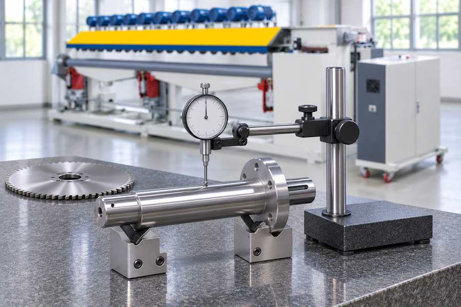
The rotating assembly must not start unexpectedly during inspection. Guards should only be removed under approved procedures, and the machine must remain safe throughout manual measurement.
Use a calibrated dial indicator or another suitable displacement-measuring instrument. Its resolution should be appropriate for the acceptance requirements rather than selected without considering the required measurement capability.
Clean the reference surfaces before positioning the indicator. Small particles, burrs, or surface damage can affect contact and produce misleading readings.
Measuring spindle radial runout
Position the indicator against a suitable cylindrical spindle reference surface. The selected location should be documented so that subsequent measurements use the same reference.
Rotate the spindle manually through one complete revolution under the defined inspection condition. Record the maximum and minimum indicator readings and calculate TIR as their difference.
Where necessary, repeat the measurement at another axial position. Comparing readings at different locations can help investigate geometric variation along the spindle reference.
Measuring spindle axial face runout
Position the indicator against the designated spindle reference face. The indicator should contact a suitable area without interfering with surrounding components.
Record the radial distance between the contact point and rotational axis. With isolation verified and hand rotation permitted by the inspection procedure, note the lowest and highest indicator positions as the spindle completes a turn.
The resulting TIR must be reported with its measurement radius. Without this information, comparisons between different measurement locations may be misleading.
Checking spindle axial endplay
Endplay requires a separate procedure. Apply a controlled axial force using an appropriate measurement arrangement and record the resulting spindle displacement.
The applied force and measurement direction should be documented. Avoid combining this result with rotational face-runout readings because they describe different mechanical conditions.
Flange and Installed-Blade Assembly Inspection
After spindle inspection, examine the flange and blade mounting interfaces where these components are accessible. The purpose is to determine whether mounting conditions contribute additional variation.
Checking flange face runout
Inspect the flange contact surfaces for contamination, burrs, scratches, and visible damage. Confirm that the contact areas are clean and that the mounting components are seated according to their specified arrangement.
Position the indicator against a suitable flange reference face. Rotate the spindle manually and record TIR at a defined measurement radius.
Where the machine design allows, compare the flange reading with an appropriate spindle reference-face measurement. This can help distinguish spindle-related variation from additional mounting-interface effects.
Checking blade axial runout
Install the blade using the specified mounting and clamping procedure. Avoid changing the installation method between measurements because inconsistent seating can affect repeatability.
Position the indicator against a suitable flat region of the blade plate. The contact point should avoid teeth, openings, markings, and other unsuitable surface areas.
For the stopped, isolated blade assembly, turn it as allowed by the inspection procedure and note both ends of the indicator’s travel. Document the measurement radius and blade mounting condition.
Repeat at additional radii when necessary. Different readings at different locations may help investigate blade geometry, mounting tilt, or local surface variation.
Checking blade radial runout
Position the indicator against a suitable blade rim or tooth-tip reference when the geometry permits. Record the location and measurement method because tooth-height differences can affect the result.
If measurements are taken at the cutting teeth, interpret the readings with the blade’s tooth geometry in mind. The result may include tooth-height variation rather than representing blade-body concentricity alone.
| Measurement | Indicator reference | Required recorded information |
| Spindle radial runout | Cylindrical spindle surface | Reference location, diameter, TIR |
| Spindle axial face runout | Spindle reference face | Face location, measurement radius, TIR |
| Spindle axial endplay | Spindle under controlled axial force | Applied force condition and displacement |
| Flange face runout | Suitable flange contact face | Reference location, measurement radius, TIR |
| Blade axial runout | Flat blade plate surface | Blade identification, radius, mounting condition, TIR |
| Blade radial runout | Suitable blade rim or tooth-tip reference | Measurement location, method, TIR |
The table provides separate inspection records rather than interchangeable accuracy figures. Each result should be compared with the acceptance requirement established for that specific component.
Repeatability also matters. If readings change significantly after remounting, investigate the measurement setup and seating conditions before attributing the difference to permanent component geometry.
Practical Diagnostic Sequence for Inconsistent Slot Width
An oversized or inconsistent slot does not identify one specific defective component. Several mechanical and operating factors may produce similar results, so diagnosis should proceed through controlled comparisons.
Verify Finished-Slot Dimensions and Cutting Conditions
Start with the engineering drawing and confirm the nominal slot width and permitted dimensional variation. Check whether the specified dimension applies to the finished opening before or after deburring.
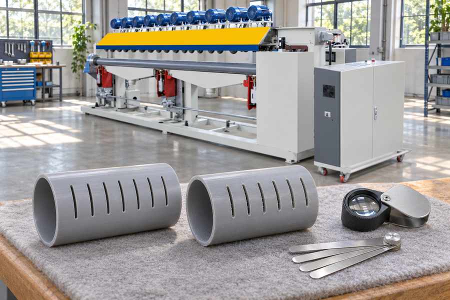
Measure multiple locations along the slot where practical. If the application requires circumferential consistency, include suitable measurement positions around the pipe.
Record individual readings rather than reporting only an average. An average can conceal localized widening, taper, or inconsistent cutting behavior.
Next, inspect the blade identification and documented cutting geometry. Confirm plate thickness, tooth width, specified kerf, and tooth condition separately.
Check for damaged teeth, uneven wear, contamination, and other visible conditions that may change the effective cutting envelope. Verify that the selected blade is appropriate for the material and cutting operation.
Inspect the pipe support and clamping arrangement. Look for possible movement, inconsistent contact, misalignment, and deformation caused by the restraint system.
Review feed conditions and cutting behavior during the trial. Vibration, unusual noise, rough edges, and changes in cutting resistance may provide additional evidence, but none independently identifies the source.
Isolate Potential Sources and Verify Through Controlled Cutting
Measure spindle radial runout with the blade removed or isolated as the machine design permits. This establishes a spindle-related reference without including the blade’s geometry.
Measure spindle axial face runout and axial endplay separately. Inspect the flange contact surfaces and record flange face runout under defined mounting conditions.
Install the blade and measure its axial and radial runout. Compare these readings with the spindle and flange measurements to identify possible additional assembly variation.
Where the mounting arrangement permits, a controlled blade-indexing or remounting comparison may provide further information. Mark the relative angular positions and repeat the measurement after an approved change in blade orientation.
Observe whether the high-reading position follows the blade or remains associated with the spindle or mounting reference. Such comparisons provide diagnostic clues, not automatic proof of a single defective component.
After component inspection, perform controlled cutting trials using the same pipe specification and documented operating conditions. Keep a trial log and alter only the setting being investigated between comparable cuts.
Compare slot-width measurements with the recorded component readings. If static runout remains consistent but cutting results change under load, investigate blade deflection, workpiece restraint, and operating conditions.
| Observed cutting result | Possible contributing factors | Recommended verification |
| Consistently oversized slots | Blade kerf, tooth geometry, blade axial runout, loaded deflection | Verify blade specification, measure installed-blade runout, inspect sample cuts |
| Slot width varies along the cutting length | Blade deflection, pipe movement, support position, changing cutting resistance | Compare measurements at several locations and inspect support conditions |
| Different widths between repeated pipe samples | Pipe dimensional variation, inconsistent clamping, blade condition, feed variation | Compare workpiece dimensions, mounting records, and cutting conditions |
| Uneven cutting edges or excessive burrs | Tooth wear, unsuitable cutting conditions, vibration, material behavior | Inspect teeth, edge condition, and cutting stability |
| Width changes under different feed conditions | Cutting-force variation, blade stiffness, chip accumulation, workpiece restraint | Conduct controlled trials while recording feed and finished-slot dimensions |
| Inconsistent results after blade replacement | Blade geometry, bore fit, flange seating, installation repeatability | Compare blade specifications, flange condition, and installed-blade measurements |
The table should guide investigation rather than replace measurement. A single observed condition may have several contributing factors, and multiple factors can occur simultaneously.
Runout Acceptance Criteria and Buyer Requirements for Pipe Slotting Machines
Runout acceptance and finished-slot acceptance should be defined separately. A machine can meet an individual component measurement requirement without necessarily producing the required slot dimensions under actual cutting conditions.
Define Measurement and Finished-Slot Acceptance Requirements
Begin by specifying the nominal slot width and permitted upper and lower limits on the engineering drawing. The drawing should also identify relevant slot positions, lengths, and dimensional relationships.
Define the finished-slot measurement method. Specify the instrument, measurement direction, contact locations, and whether the inspection applies before or after deburring.
Establish separate acceptance requirements for spindle radial runout, spindle axial face runout, axial endplay, flange face runout, and installed-blade runout.
Each requirement should identify its reference surface and measurement condition. For face measurements, include the indicator radius because the reported TIR depends on where contact occurs.
Acceptable runout values should be established from the machine design, blade requirements, cutting geometry, and intended application. There is no single universal TIR limit suitable for every pipe slotting configuration.
Measurement uncertainty must also be considered. An instrument with insufficient resolution or an inconsistent contact arrangement cannot reliably establish whether a small dimensional requirement has been satisfied.
Buyers should ask how the supplier distinguishes spindle-only readings from installed-assembly readings. This clarification prevents an overall blade measurement from being incorrectly treated as a spindle specification.
Conduct Sample Cutting Trials and Confirm Machine Suitability
A sample cutting trial should represent the actual production application as closely as practical. Before the first cut, log the sample’s material grade, measured diameter, wall thickness and surface condition.
The trial specification should identify the intended blade and its cutting geometry. Feed conditions, support arrangement, clamping method, and other relevant settings should also be recorded.
Agree on the sample quantity and measurement locations before the trial begins. Repeated samples are more useful than one isolated result when evaluating process consistency.
Inspect each sample against the agreed slot-width requirements. Record variation between locations and individual workpieces rather than relying only on average dimensions.
Burr condition and cutting-edge quality should also be documented. If deburring is part of the intended production process, establish whether acceptance measurements apply before or after that operation.
Component inspection and cutting trials should complement each other. Spindle, flange, and blade measurements help evaluate the mechanical assembly, while sample parts demonstrate the combined result under the selected operating conditions.
Evaluating Yuyu Machinery machine options
Buyers can begin by reviewing the Yuyu Machinery pipe slotting machine range to identify equipment options for their pipe-processing requirements.
The DS250-SA pipe slotting machine has a published pipe diameter range of 75–250 mm and a pipe length range of 3–6 m.
These dimensions describe the stated general workpiece envelope. They do not establish spindle radial runout, axial face runout, blade runout, or a guaranteed finished-slot width tolerance.
The actual spindle arrangement, blade mounting interface, clamping configuration, and available measurement references should be confirmed with Yuyu Machinery. Buyers should not assume a particular blade or restraint arrangement without configuration-specific information.
Before purchase approval, agree on the measurement procedure and sample-cutting conditions. The acceptance document should identify both component-level requirements and finished-part dimensional criteria.
A drawing and trial request should include the pipe material, outside diameter, wall thickness, pipe length, slot width, slot length, slot spacing, and required dimensional tolerances.
It should also identify the blade specification and cutting kerf, proposed feed conditions, workpiece restraint requirements, measurement locations, burr acceptance condition, separate spindle and blade TIR requirements with reference radii, and the sample quantity required for final acceptance.