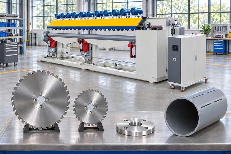
Blade diameter defines a tool’s nominal cutting envelope, not the usable depth a pipe slotting machine can achieve. Flange clearance, spindle position, machine travel, pipe geometry, and operating limits determine actual access.
Buyers must assess the complete installed cutting path, particularly when the workpiece is curved, dimensionally variable, or built with separate outer and inner walls.
Understanding Blade Diameter and Exposed Radial Reach
Blade Diameter, Radius, and Cutting-Tooth Envelope
Blade diameter is the overall distance measured across opposing cutting-tooth tips. It describes the cutting tool’s nominal size and provides an initial reference for evaluating potential penetration.
Blade radius is half the nominal diameter, measured from the spindle center to the cutting-tooth envelope. This radius helps establish the blade’s theoretical radial reach before considering mounting obstructions.
However, the blade’s cutting envelope is not necessarily identical to the dimensions of its supporting plate. Tooth geometry, cutting-edge arrangement, and wear can influence the effective outer boundary.
For engineering calculations, buyers should use the actual cutting-tooth envelope rather than assume every blade has a perfectly circular, uninterrupted cutting edge.
The distinction matters because the blade plate, mounting flange, and cutting teeth occupy different regions around the spindle. Each component can influence access to the pipe surface.
A blade may have a relatively large nominal diameter while providing limited access near its mounting assembly. Conversely, a smaller blade with suitable mounting geometry may provide sufficient exposed reach.
Blade diameter therefore serves as a starting measurement, not a complete machine-selection specification. Its practical value depends on the surrounding components and required cutting path.
Exposed Radial Reach Beyond the Flange
Exposed radial reach describes how far the cutting-tooth envelope extends beyond the outer edge of the mounting flange. It indicates the blade’s available radial extension outside this particular obstruction.
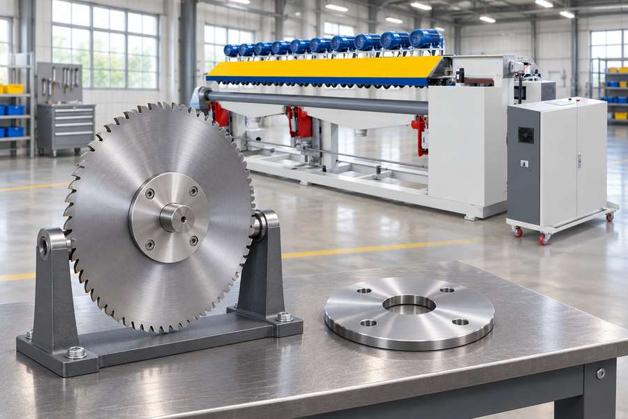
For a concentric installation where the flange is the governing obstruction, a simplified relationship is:
Exposed radial reach ≈ Blade radius − Flange radius
For example, consider a hypothetical blade radius of 100 mm and a mounting flange radius of 35 mm. The simplified exposed radial reach would be approximately 65 mm.
This calculation assumes the blade and flange share the same centerline, and their relevant outer boundaries are circular. Actual installations may contain additional obstructions.
A spindle housing, stepped mounting component, or adjacent structure may extend farther into the cutting region. In those cases, flange radius alone cannot describe the complete clearance.
The calculation also does not account for machine positioning, pipe curvature, blade deflection, or the distance between the spindle center and pipe surface.
Exposed radial reach must not be interpreted as guaranteed cutting depth. It describes a geometric relationship between two components, not the final penetration achievable under operating conditions.
Another important distinction concerns blade tooth protrusion. This term describes how far cutting teeth extend beyond the blade plate, rather than how far the blade extends beyond its mounting flange.
For equipment selection, exposed radial reach beyond the flange is the more useful measurement when evaluating mounting-related restrictions. Tooth protrusion should remain a separate blade-construction specification.
| Measurement | Definition | Relevance to cutting access | Main limitation |
| Blade diameter | Overall diameter across cutting-tooth tips | Establishes nominal tool size | Does not guarantee cutting depth |
| Blade radius | Distance from spindle center to tooth-tip envelope | Establishes theoretical radial reach | Excludes mounting obstructions |
| Flange radius | Distance from flange center to its outer edge | Identifies a mounting obstruction | May not represent the largest obstruction |
| Exposed radial reach | Blade radius minus flange radius under concentric conditions | Estimates available reach beyond the flange | Excludes machine movement and pipe geometry |
| Tooth protrusion | Tooth extension beyond the blade plate | Describes cutting-edge construction | Does not establish flange clearance |
Machine Travel, Spindle Position, and Installation Clearance
Spindle Position and Available Cutting Movement
Even when blade geometry provides sufficient theoretical reach, the machine must position the spindle correctly to access the intended pipe wall.
Spindle center position determines the blade’s relationship with the pipe surface. Its height, orientation, and distance from the workpiece influence where cutting engagement begins.
A blade mounted too far from the required cutting position may fail to reach the intended wall. Increasing its diameter might improve geometric reach, but could introduce other compatibility problems.
Machine movement must also be considered independently from blade dimensions. A machine may provide sufficient blade radius but insufficient travel to complete the required cutting operation.
Available travel describes the permitted movement of the relevant machine assembly. Effective cutting stroke represents the portion of that movement actually usable after considering approach and clearance requirements.
The distinction is important when the blade must enter from a specific direction. Initial clearance, starting position, and stopping position all influence the available cutting movement.
Radial positioning and axial feed should also be treated as separate movements. Radial movement changes the blade’s relationship with the pipe surface, while axial movement changes its position along the pipe.
Depending on the machine configuration, other positioning movements may also influence the cutting path. Buyers should identify which axes control approach, penetration, and slot positioning.
A complete assessment therefore requires more than checking the spindle’s maximum travel specification. The relevant question is whether the installed blade can follow the required path without interference.
The Complete Installed Interference Envelope
The blade should be evaluated as part of the complete installed assembly rather than as an isolated cutting component.
Potential obstructions include the mounting flange, spindle housing, machine frame, clamps, pipe supports, guards, and nearby structural components. Their relevance depends on the actual equipment arrangement.
Interference may occur before the cutting teeth reach their intended position. A flange or housing can contact the pipe surface even when the cutting edge still has theoretical clearance.
The same problem can occur during movement. An assembly that clears the workpiece at its starting position may encounter interference as the spindle advances.
Buyers should therefore examine the swept envelope, meaning the space occupied by the installed assembly throughout its required movement. This evaluation should include the blade and surrounding components.
The assessment must consider both the workpiece and machine sides. Pipe positioning, clamping arrangements, and support locations can change the available space around the cutting area.
A larger blade does not automatically solve insufficient clearance. It may increase radial reach while also requiring more surrounding space and greater compatibility with the spindle assembly.
For purchasing decisions, the machine configuration should be confirmed against the actual pipe section and cutting requirements. Undocumented spindle positions, clamp designs, or mounting arrangements should never be assumed.
Yuyu Machinery’s pipe slotting machine range provides a starting point for evaluating equipment options against the intended pipe dimensions and production requirements.
The buyer should then request confirmation of the relevant cutting arrangement, available movement, mounting dimensions, and physical clearance before specifying a blade diameter.
How Pipe Geometry Affects Actual Through-Wall Cutting Depth
Outside Diameter, Wall Thickness, and Ovality
Pipe outside diameter determines the overall curvature of the workpiece and influences the blade’s initial contact position. Wall thickness determines the material distance that must be penetrated.
These dimensions describe different aspects of the pipe. A large outside diameter does not necessarily indicate a thick wall, while a smaller pipe may have comparatively substantial wall thickness.
The required cutting path must be evaluated against the actual cross-section at the intended slot location. Nominal dimensions alone may not describe local conditions adequately.
For a simple radial section, the approximate distance from the outside surface to the inside surface corresponds to local wall thickness. However, this does not establish the safe machine stroke.
The installed spindle position, approach direction, pipe support, blade envelope, and stopping position must also be considered. Their combined geometry determines whether the intended wall can be reached safely.
Pipe ovality introduces another variable. An oval pipe has different outside dimensions along different measurement directions, changing the local surface position relative to the blade.
If the pipe is positioned using only its nominal diameter, the actual cutting distance may vary around its circumference. This can produce inconsistent penetration between different slot positions.
Buyers should specify the acceptable pipe dimensional range and identify the measurement location. Representative samples can help establish whether ovality requires additional positioning or support consideration.
Wall thickness variation also matters. The thickest and thinnest sections may present different penetration requirements, particularly when the machine processes pipes from multiple production batches.
The equipment specification should distinguish nominal wall thickness from its permitted variation. A trial based on one convenient sample cannot automatically demonstrate suitability for every pipe within the intended range.
Cutting Direction, Curved Surfaces, and Pipe Support
A circular blade approaching a curved pipe surface encounters changing surface positions across the cutting area. The resulting slot geometry depends on blade orientation and penetration location.
A straight-line measurement through the projected pipe profile is not necessarily equal to the distance measured along the curved surface.
Define the slot-length measurement before comparing two proposed cutting depths. Buyers should identify whether the required dimension represents actual surface length, projected chord length, or another drawing-defined measurement.
For a simplified circular cross-section, a chord connects two points on the circumference directly. The corresponding arc follows the curved surface between those same points.
The arc is longer than its corresponding chord, but the relationship depends on the angular span. It should not be used as a universal correction without the actual pipe geometry.
Blade orientation also influences the opening. A blade approaching at an angle may produce a different slot profile from one entering perpendicular to the local cutting surface.
Consequently, slot depth, slot length, and slot width should be specified independently. One dimension cannot reliably substitute for another when evaluating finished-part requirements.
Pipe support introduces additional geometric considerations. An unsupported section may move or deflect under cutting forces, changing the relationship between the pipe surface and blade.
Clamping locations can also restrict blade access. A clamp positioned too close to the intended slot may interfere with the blade, flange, or surrounding assembly.
The support arrangement should hold the pipe in its intended operating position without introducing unacceptable distortion. Buyers should verify both stability and physical access.
Inspection should include the pipe’s position before cutting and its condition after release. This helps distinguish cutting-related dimensional problems from deformation caused by clamping or support.
Through-Wall Access in Corrugated and Double-Wall Pipes
Corrugation Geometry and the Required Cutting Path
Corrugated pipes present a more complicated cutting profile than pipes with relatively uniform cylindrical walls. Their outer surfaces alternate between crests and valleys.
The blade encounters different local surface positions depending on where the slot begins. A cutting path through a crest may require different penetration from one passing through a valley.
Nominal outside diameter does not fully describe these local differences. The actual corrugation profile and wall arrangement must be examined using a representative pipe section.
Corrugation pitch and profile height can also influence the available cutting position. These dimensions determine how frequently the surface changes and how much the local geometry varies.
A blade selected using only the maximum outside diameter may therefore provide an incomplete basis for determining penetration requirements.
The cutting direction should be defined relative to the corrugation profile. Buyers should establish whether the slot crosses a crest, follows a valley, or intersects several profile features.
Support becomes particularly important when the cutting area is not directly backed by a stable structural section. Local deformation can change the intended cutting path.
A sectional drawing should identify the outer profile, local wall thickness, and intended slot location. This allows the blade envelope to be compared with the actual pipe structure.
Reaching the Inner Liner Without Damaging Other Layers
Double-wall pipes require separate consideration of the outer corrugated wall, intervening space, and inner liner. Reaching the inner layer involves more than penetrating the outside profile.
The distance between the outer surface and inner liner depends on the actual pipe construction. It may vary between corrugation crests, valleys, and other profile locations.
Nominal outer-wall thickness is therefore insufficient for establishing the total cutting path. The complete cross-section must show where the intended inner surface is located.
Buyers should identify which layers must be cut and which must remain intact. A slot specification should clearly distinguish outer-wall access from inner-liner penetration.
Excessive penetration may damage the inner liner beyond the intended opening. Depending on the application, this can affect the pipe’s structural or functional requirements.
Insufficient penetration creates the opposite problem. The outer wall may appear cut while the intended opening through the inner layer remains incomplete.
Machine travel must be coordinated with blade geometry and the actual pipe position. The stopping position should account for the installed arrangement rather than simply equal nominal wall thickness.
The opposite pipe wall also requires protection. A blade with sufficient reach to access the near-side structure may create unwanted contact if positioning or penetration is not controlled.
For these applications, a representative cross-sectional drawing and physical trial are especially important. The acceptance criteria should identify the intended cutting boundary and acceptable condition of every affected layer.
Blade Stiffness, Compatibility, and Safe Operating Limits
Blade Stiffness and Cutting Deflection
Geometric clearance does not guarantee that the blade will maintain its intended cutting path under operating loads. Tool stiffness and machine rigidity also influence actual cutting performance.
Blade stiffness depends on construction, including plate thickness, material properties, diameter, and supporting arrangement. These characteristics should be evaluated for the intended cutting application.
A larger diameter may increase the unsupported distance between the cutting region and supporting structure. Depending on the blade design, this can influence deflection under cutting forces.
Deflection may change the effective cutting position. It can contribute to slot-width variation, uneven material removal, or contact with surfaces outside the intended cutting path.
Blade movement should be distinguished from spindle movement. The blade may flex while the spindle remains correctly positioned, or the spindle assembly itself may move under load.
Machine structural deflection introduces another possible source of displacement. The support frame and positioning components must maintain the required relationship between the blade and workpiece.
Check the contribution of each source separately before choosing any setting allowance. Their magnitude depends on the actual machine, blade, material, and cutting conditions.
Buyers should ask how the proposed blade and mounting arrangement are supported. Relevant information includes permitted blade dimensions, plate construction, mounting conditions, and operating restrictions.
The purpose is not to select the stiffest possible blade regardless of other factors. The selected tool must provide adequate cutting performance while remaining compatible with the machine and required slot geometry.
Spindle Compatibility, Speed Rating, and Guarding
Blade diameter must be checked against spindle compatibility before equipment selection. The spindle and mounting assembly must accommodate the blade’s actual dimensions and intended operating conditions.
Relevant mounting information includes bore diameter, mounting flange dimensions, seating surfaces, and the permitted blade configuration. A matching nominal diameter does not establish mechanical compatibility.
Rotational speed is another important consideration. Keep the same rpm and each tooth on a wider disc covers a longer circular path per minute.
To calculate the cutting-edge travel rate, use the installed blade diameter together with the selected rpm. For a blade diameter expressed in metres, it can be estimated using:
Peripheral speed = π × Blade diameter × Rotational speed / 60
The result is expressed in metres per second when rotational speed is given in revolutions per minute.
This relationship helps explain why blade diameter cannot be increased independently of operating speed. The permitted combination must comply with the blade manufacturer’s rating and machine restrictions.
Buyers should confirm the applicable speed limits before approving a replacement or alternative blade. Neither theoretical cutting reach nor improved clearance justifies exceeding rated operating conditions.
Guarding must also accommodate the installed blade and its required movement. The guard, frame, and nearby structures must provide appropriate physical clearance during operation.
A blade that fits the spindle may still be unsuitable if the installed assembly cannot operate within the required guarded space.
Chip evacuation and inspection access should also be considered where relevant. Restricted space around the cutting area may complicate cleaning, observation, and routine maintenance.
Removing guards or bypassing safety devices is not an acceptable response to insufficient clearance. If the proposed blade cannot operate within the approved safety arrangement, its suitability must be reassessed.
How to Verify Required Cutting Depth Before Machine Release
Review the Pipe and Machine Section Drawing
A sectional drawing provides a more reliable basis for evaluating through-wall access than a blade diameter specification alone. It should show the relationship between the pipe, blade, spindle, and relevant machine components.
The pipe cross-section should identify outside diameter, wall thickness, ovality, and any relevant dimensional variation. Double-wall constructions should also show the inner liner and intervening space.
The blade assembly should include nominal diameter, cutting-tooth envelope, flange dimensions, and the calculated exposed radial reach beyond the flange.
The drawing should identify the spindle centerline, blade orientation, approach direction, and available machine movement. These details establish the blade’s position relative to the intended cutting surface.
Relevant surrounding components should also appear. Clamps, supports, guards, spindle housings, and other possible obstructions can affect the actual swept envelope.
The intended slot should be dimensioned independently. Required cutting depth, width, length, position, and acceptable remaining material should be clearly identified.
For curved surfaces, the drawing should specify whether slot length refers to surface measurement or projected chord measurement. This prevents different interpretations during equipment approval and finished-part inspection.
The drawing should also identify the required cutting boundary. Where an inner liner must be reached, its intended penetration and protection requirements should be shown explicitly.
A useful review compares the complete blade and machine movement envelope against the pipe section. It should identify potential interference throughout the cutting operation, not just at the initial position.
Conduct a Representative Cutting Trial
A drawing-based assessment should be followed by a representative cutting trial when the application requires confirmation of actual through-wall access.
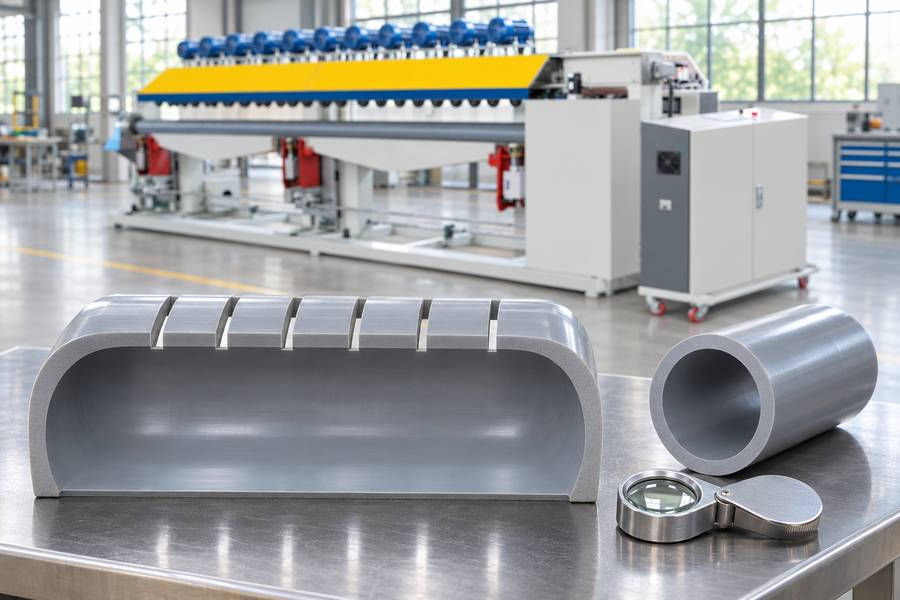
The sample should represent the intended pipe construction and relevant dimensional variations. Testing only a nominal sample may overlook differences in ovality, wall thickness, or corrugation geometry.
Before testing, confirm the proposed blade, mounting arrangement, spindle compatibility, and permitted rotational speed. The installed guard and surrounding clearances should also be checked.
The trial should examine the complete cutting movement. Observe whether the blade reaches the intended location without contacting the flange, housing, clamp, support, or other surrounding components.
The actual finished opening should then be compared with the drawing. A visible slot does not automatically demonstrate that the required wall section has been penetrated completely.
For double-wall pipes, inspect the outer wall and inner liner separately. Confirm that the intended layers have been accessed without unwanted deformation or excessive material removal.
The trial should also consider pipe movement during cutting. If the workpiece shifts, the resulting opening may not represent the accuracy achievable under the intended production arrangement.
Repeatability matters when the machine will process a range of pipe dimensions. The approved setup should be evaluated against the specified operating range rather than treated as suitable for every possible variation.
Yuyu Machinery’s DS250-SA pipe slotting machine provides a reference for discussing published machine working dimensions. Its listed pipe diameter range is 75–250 mm, with pipe lengths of 3–6 m.
These figures describe the model’s published general working envelope. They do not establish a specific blade diameter, flange configuration, spindle travel, cutting depth, or double-wall penetration capability.
Have the supplier check the proposed setup against the pipe section and slot drawing before accepting the tooling choice. The product’s general dimensional range should not replace a drawing-based technical review.
Combine Finished-Part Inspection and Equipment Release
The finished slot should be inspected against agreed drawing requirements. Acceptance should cover both dimensional accuracy and the condition of surrounding pipe material.
Cutting depth must be checked at the specified location. Where wall thickness varies, the inspection method should distinguish complete penetration from excessive removal.
Slot width should be measured at appropriate positions along the opening. This helps identify irregular cutting caused by blade deflection, positioning errors, or workpiece movement.
Slot length should follow the drawing’s measurement definition. Surface length and projected chord length should not be treated as interchangeable acceptance dimensions.
Remaining material requires particular attention when only selected pipe layers should be cut. Inspection should confirm that unintended penetration has not occurred.
For double-wall pipes, inner liner inspection should identify incomplete openings, unwanted cuts, and deformation. The opposite wall should also be checked where the cutting path creates a potential contact risk.
The machine itself requires a corresponding clearance review. Confirm that the installed blade completes the required movement without interference under the approved configuration.
Release records should identify the blade dimensions, mounting arrangement, spindle position, relevant travel settings, pipe sample dimensions, and operating conditions used during verification.
Any change to blade diameter, flange geometry, pipe construction, or support arrangement may alter the cutting envelope. Such changes should trigger an appropriate engineering review before the revised setup is accepted.
The final drawing and trial request should include:
- Pipe geometry: Outside diameter and tolerance range, minimum and maximum wall thickness, ovality, corrugation profile, and inner liner position.
- Tool and movement: Blade diameter, flange dimensions, spindle center position, available travel, and cutting direction.
- Slot and installation: Required slot depth, width and surface length, support and clamping locations, guarding constraints, permitted rotational speed, and finished-part acceptance criteria.