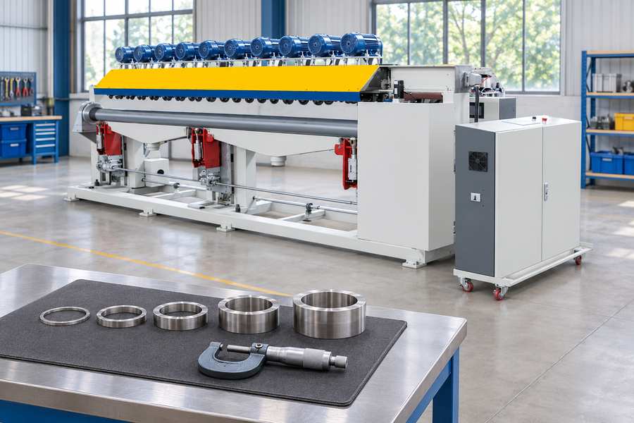
Blade spacer tolerances determine how blades are positioned in a multi-blade pipe slotting machine, but spacer thickness alone does not define center pitch, cutting kerf, or finished slot width.
A reliable specification connects component dimensions, datums, stack-up limits, geometric controls, and inspection conditions to the required pipe slot pattern and confirmed machine configuration before tooling is ordered.
Understand the Key Dimensions in a Multi-Blade Assembly
Before specifying tolerances, buyers must distinguish individual component dimensions from the cutting geometry produced by an assembled blade stack. Treat each measurement as a separate drawing requirement; agreement on one dimension says little about the others.
A spacer controls the separation between adjacent blade faces, while blade body thickness also contributes to the distance between blade center planes. Cutting geometry introduces additional variables that component measurements cannot establish independently.
Five dimensions are particularly important when preparing a blade spacer specification.
Blade center pitch: This is the center-to-center distance between adjacent blade reference planes. It determines the nominal spacing between neighboring cutting positions and ultimately influences the spacing between finished pipe slots.
Spacer thickness: This is the physical distance between two opposing spacer contact faces. It establishes part of the axial separation between adjacent blades, but does not independently determine their center pitch.
Blade body thickness: This refers to the thickness of the blade plate, measured away from teeth and other cutting features. Include the measured plate thickness in the center-pitch calculation for every neighboring pair.
Cutting kerf: Kerf represents the width of material removed during cutting. Tooth geometry, side grinding, blade condition, runout, and operating conditions can influence the actual cutting width.
Finished slot width: This is the measured opening remaining in the pipe after cutting. Material deformation, burr formation, cutting conditions, and the specified finishing procedure can affect the final measurement.
Distinguish Component Dimensions from Cutting Results
Blade body thickness and cutting kerf should never be treated as interchangeable specifications. A blade may have a relatively thin body while its cutting teeth extend farther outward.
Tooth set or side grinding can produce a cutting envelope wider than the blade plate. Consequently, measuring the blade body does not establish the actual material removal width.
Finished slot width also requires independent verification. The opening remaining in a pipe can differ from the nominal cutting envelope because of material behavior and subsequent processing.
Similarly, blade center pitch describes the positioning of cutting tools, not necessarily the measured distance between finished slot edges. Buyers should specify slot center spacing and slot width separately.
| Dimension | Measurement Reference | Primary Function | Verification Method |
| Blade center pitch | Adjacent blade center planes | Slot center spacing | Assembled position measurement |
| Spacer thickness | Opposing spacer faces | Blade positioning | Micrometer measurement |
| Blade body thickness | Blade plate | Component geometry | Thickness measurement |
| Cutting kerf | Material removed | Cutting width | Controlled cutting trial |
| Finished slot width | Actual pipe opening | Final product dimension | Slot inspection |
These distinctions establish the foundation for tolerance allocation. Without them, a technically acceptable spacer can still produce an assembled blade position or finished slot pattern that does not meet purchasing requirements.
Define Slot Pattern Requirements and Measurement Datums
Tolerance selection should begin with the required finished pipe geometry rather than an assumed standard spacer thickness. Buyers first need to establish the slot arrangement and identify the machine references controlling blade positions.
The specification should describe both individual slot dimensions and their relationships across the entire pipe. This prevents local dimensional requirements from being confused with overall positioning accuracy.
Define the Required Pipe Slot Pattern
Start by identifying the nominal slot width, center pitch, number of slots, and overall arrangement. These characteristics establish the dimensional targets that the blade assembly must produce.
Pipe diameter, wall thickness, and material should also be documented. They influence the cutting application and help determine whether the proposed blade arrangement is suitable for the intended workpiece.
For applications requiring axial positioning, specify the distance between each slot and the selected pipe-end reference. Include end margins and any intentional differences between individual slot positions.
Circumferential positioning also needs attention when the required pattern extends around the pipe. Define the intended angular relationship between cutting positions and the reference used to orient the workpiece.
Buyers should distinguish equal-spacing patterns from arrangements containing deliberately different intervals. Applying one center-pitch tolerance to every position would be inappropriate if the drawing specifies multiple nominal distances.
The finished-product drawing should therefore identify:
- Nominal slot width and permissible variation.
- Nominal center pitch between adjacent slots.
- Total number of slots and their arrangement.
- Axial reference and required end distances.
- Circumferential orientation where applicable.
- Overall positional requirements for the completed pattern.
Establish Machine Datums and Nominal Blade Positions
A datum system provides the reference needed to measure blade positions consistently. Without clearly defined references, two inspection procedures may produce different reported dimensions even when examining the same assembly.
The arbor axis may serve as a radial reference when the machine uses an arbor-mounted blade arrangement. Show the proposed radial datum on the assembly drawing and have the machine supplier confirm that reference.
An axial locating shoulder or reference face may establish the starting position of the blade stack. The first blade center plane can then be dimensioned relative to that reference.
Buyers should identify the relationship between the machine datum and the pipe-positioning system. The pipe fixture, axial stop, and rotational reference may all influence the final slot coordinates.
Nominal blade positions can then be calculated from the required slot pattern. Each position should have an identifiable reference rather than relying exclusively on the distance from the preceding blade.
The distinction matters because controlling adjacent pitch does not automatically control the absolute location of the first blade. An error in the initial reference can shift the entire slot pattern.
The selected machine architecture must also be considered before finalizing the drawing. Reviewing the pipe slotting machine product range helps buyers identify which configuration-specific dimensions require confirmation.
Do not assume that every multi-blade machine uses identical arbor dimensions, locating shoulders, spacer arrangements, or blade retention methods. These details must come from the confirmed machine configuration.
Specify Blade and Spacer Dimensions and Geometric Tolerances
Once nominal blade positions and datums are established, individual component drawings can define the dimensional and geometric requirements. Spacer thickness, blade body thickness, bore dimensions, and contact-face accuracy should receive separate specifications.
A useful drawing distinguishes characteristics that directly control positioning from those that influence assembly quality. This approach avoids assigning unnecessary tolerances to dimensions without a demonstrated functional purpose.
Specify Spacer Thickness and Blade Body Dimensions
Spacer thickness should have a clearly identified nominal dimension and permitted variation. Buyers can select bilateral or unilateral tolerances according to the required positioning arrangement.
The measurement procedure should define where thickness is checked. Measurements at several specified locations help identify local variation that a single central measurement might overlook.
For example, a spacer could have an acceptable average thickness while its opposing faces are not sufficiently parallel. Such a component may produce inconsistent seating when installed between blades.
Therefore, the drawing should distinguish nominal thickness from local thickness variation. Where multiple spacers are combined into one inter-blade position, their combined dimensions must also be considered.
Blade body thickness requires a similarly clear measurement definition. The inspection area should exclude teeth, tooth set, and other cutting features unless the drawing specifically requires those characteristics.
A blade’s body thickness contributes to adjacent center pitch. Consequently, the blade supplier’s dimensional variation should be included in the tolerance calculation rather than treated as unrelated to spacer accuracy.
When several blades are installed together, differences between individual blade thicknesses can create different center pitches even when every spacer has the same nominal thickness.
Buyers should also establish whether the positioning calculation references the physical blade body center plane or another defined reference plane. This distinction becomes important when blade geometry is asymmetric.
Define Geometric Controls, Bore Fit, and Surface Requirements
Dimensional thickness accuracy does not guarantee suitable contact geometry. Flatness and parallelism determine whether opposing spacer faces can seat consistently within the intended assembly.
Flatness: This controls the form of an individual contact face. Excessive deviation can create localized contact rather than the intended supporting surface.
Parallelism: This controls the relationship between opposing faces. Poor parallelism can produce different effective spacer thicknesses across the contact area.
Perpendicularity: Where functionally relevant, the relationship between spacer faces and the bore axis should also be defined. This helps evaluate whether the component’s mounting geometry is consistent with the intended arrangement.
These controls should be selected according to actual functional requirements. Assigning extremely restrictive geometric tolerances without considering the machine structure can increase manufacturing cost without improving finished slot accuracy.
Spacer bore diameter must be specified relative to the actual arbor dimensions. The required fit depends on the mounting architecture, positioning method, and retention arrangement.
Excessive clearance may permit unwanted movement or reduce positioning repeatability. Conversely, an unsuitable interference fit can make installation difficult or introduce unwanted mechanical stress.
Buyers should not automatically select a standard clearance or interference class. The machine drawing and confirmed assembly requirements should determine the appropriate fit.
Contact-face surface condition also deserves attention. Burrs, dents, raised material, and contamination can prevent full seating even when measured dimensions satisfy the drawing.
Chamfers and edge breaks should be documented where they affect contact or assembly. Surface finish requirements should likewise be included only when they influence positioning, seating, or functional performance.
Choose Gauges for the Specified Component Features
Select the gauge after deciding which spacer feature the drawing controls and where the reading must be taken. A micrometer is appropriate for spacer and blade thickness, while a suitable bore gauge can verify internal diameter.
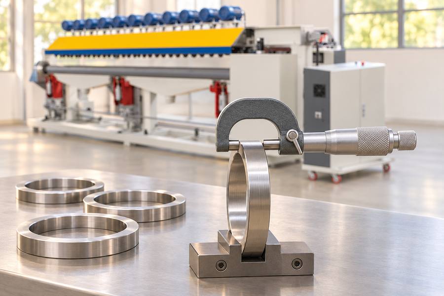
Flatness and parallelism require appropriate geometric inspection equipment and clearly defined reference conditions. The selected method should provide sufficient resolution for the specified acceptance limits.
For critical spacer dimensions, the inspection plan should identify measurement locations around the component. This allows local thickness variation to be distinguished from the overall dimensional result.
Instrument calibration and measurement repeatability also matter. An instrument’s displayed resolution alone does not establish that the inspection method can reliably distinguish acceptable components from nonconforming ones.
Log each reading against the part identifier and drawing version, alongside the gauge used and the inspection location. These records make it easier to investigate dimensional differences during later assembly.
Calculate Blade Stack-Up and Evaluate Cumulative Tolerance
A multi-blade assembly contains several interacting dimensions. Individual spacer and blade deviations influence adjacent center pitches, while their combined effects determine the position of blades farther along the stack.
The calculation must follow the actual component arrangement. Buyers should document every interposed spacer, shim, and locating component before calculating nominal positions or allowable deviations.
Calculate Adjacent Blade Center Pitch and Total Stack Span
Consider an arrangement in which one spacer or a combined spacer pack separates two adjacent blades. The center pitch can be calculated using:
P_i = S_i + (T_i + T_(i+1)) / 2
Where:
- P_i is the center pitch between adjacent blades.
- S_i is the combined thickness of spacer material between those blades.
- T_i is the body thickness of the first blade.
- T_(i+1) is the body thickness of the next blade.
The equation accounts for the distance between the two blade contact faces and the distance from each face to its blade center plane.
When adjacent blades have equal body thickness, the relationship simplifies to:
P = S + T
This simplified expression is useful for preliminary calculations, but it should not replace individual measurements when blade thicknesses vary.
The calculation assumes that the blades are located through the specified face-to-face spacer arrangement. If the actual machine uses another locating architecture, the dimensional relationship must be derived from its assembly drawing.
For an assembly containing several blades, the distance between the first and final blade center planes requires a different expression.
For n blades separated by n-1 spacer packs:
C_(1-to-n) = T_1/2 + S_1 + T_2 + S_2 + … + T_(n-1) + S_(n-1) + T_n/2
This expression reveals an important feature of cumulative stack-up. The first and final blades contribute half their body thicknesses, while every internal blade contributes its full thickness.
Each spacer pack between adjacent blades contributes its complete combined thickness. Additional components must be included according to their actual position and function in the stack.
Evaluate Local and Cumulative Dimensional Errors
Adjacent pitch errors and final blade position errors describe different aspects of assembly accuracy. A local pitch deviation changes the distance between two neighboring blade centers.
When several adjacent positions are combined, their deviations influence the location of the final blade. Errors can accumulate even when individual pitch measurements appear relatively small.
The relationship becomes clearer when the full stack is expressed through its original component dimensions. Each internal blade appears once as a complete thickness, rather than appearing as two independent half-thickness contributions.
This distinction is essential when calculating tolerance limits. Treating every adjacent pitch as an independent dimension can count shared blade thickness errors incorrectly.
For example, the second blade’s thickness contributes half to the first adjacent pitch and half to the next. Across the complete span, those two contributions combine into one full blade thickness.
A total stack-length measurement alone also cannot prove that every individual center pitch is correct. Different combinations of component deviations can produce the same overall stack length.
Therefore, buyers should establish separate requirements for adjacent blade pitch and cumulative blade position. The overall stack dimension should be controlled where it has a functional relationship with the machine’s locating arrangement.
Select the Appropriate Tolerance Analysis Method
Worst-case arithmetic accumulation is suitable when the specification requires the assembled dimension to remain within defined limits under all permitted component deviations.
For a first-to-last center span, the worst-case dimensional variation can be evaluated using the same coefficients as the nominal stack formula. Spacer deviations contribute fully, internal blade thickness deviations contribute fully, and end-blade thickness deviations contribute half.
This method can produce a more restrictive component tolerance allocation. However, it provides a direct way to assess whether permitted component limits can guarantee the required assembled dimensional boundary.
Statistical analysis may be useful when sufficient manufacturing data exists. Root-sum-square calculations can estimate variation under appropriate assumptions, but they are not automatically equivalent to guaranteed limits.
The underlying dimensions must be considered rather than treating every adjacent pitch error as an independent random variable. Adjacent pitches share blade thickness dimensions, creating a mathematical relationship between their variations.
For a complete stack span, statistical analysis should use the original component variables and their appropriate coefficients. Where dimensions are correlated, covariance terms must also be included.
Common manufacturing shifts, shared machining setups, and lot-related variation can create correlations between components. Ignoring these relationships may understate the expected assembly variation.
A statistical tolerance method should therefore document its input distributions, process stability, independence assumptions, and correlation treatment. Without supporting data, worst-case analysis is generally more defensible for guaranteed dimensional acceptance.
Use a Hypothetical Stack-Up Example
Consider a hypothetical assembly containing three blades and two spacer packs. Assume each blade body is nominally 4.00 mm thick and each spacer pack is 6.00 mm thick.
The nominal center pitch between either pair of adjacent blades is 10.00 mm. The first-to-third blade center span is therefore 20.00 mm.
Now consider hypothetical measured deviations from nominal. The first blade is 0.02 mm thicker, the second is 0.01 mm thinner, and the third is 0.03 mm thicker.
Assume the first spacer pack is 0.02 mm thicker and the second is 0.01 mm thinner than their nominal dimensions. These are illustrative deviations, not proposed manufacturing tolerances.
The first-to-third center-span deviation becomes:
0.5(0.02) + 0.02 – 0.01 – 0.01 + 0.5(0.03) = 0.025 mm
The result demonstrates how end blades contribute half their thickness deviations while the internal blade contributes its complete deviation.
The two spacer deviations also contribute fully. This calculation provides a transparent basis for reviewing component tolerance allocation before ordering a complete blade assembly.
Table 2. Main Blade Stack-Up Tolerance Contributors
| Characteristic | Contribution to First-to-Last Center Span | Specification Focus | Verification |
| First blade thickness | Half its thickness variation | Body thickness | Micrometer |
| Internal blade thickness | Full thickness variation | Individual blade dimensions | Micrometer |
| Final blade thickness | Half its thickness variation | Body thickness | Micrometer |
| Inter-blade spacer pack | Full combined thickness variation | Total spacer thickness | Dimensional inspection |
| First-blade locating position | Shifts the complete blade pattern | Datum-based position | Axial measurement |
| Contact-face geometry | Can affect effective seating | Flatness and parallelism | Geometric inspection |
| Arbor and locating features | Influence mounted positioning | Fit and alignment | Assembly inspection |
Verify Assembly Accuracy and Finished Cutting Performance
Individual components may satisfy their drawings without producing an accurate assembled blade stack. Assembly conditions, mounting fit, and geometric alignment must therefore be checked before evaluating actual cutting performance.
The inspection process should distinguish component compliance, assembled tooling accuracy, and finished pipe dimensions. Each stage answers a different question and requires its own acceptance criteria.
Inspect Assembly Conditions and Mounted Blade Alignment
Before installation, contact faces should be clean and free from raised material. Small burrs or trapped particles can prevent components from seating against their intended mating surfaces.
The specified blade and spacer order must be followed. Reversing components or introducing unauthorized shims can change the assembled dimensions even when every individual component is acceptable.
Clamping should follow the approved machine procedure. Excessive or inconsistent clamping force may influence seating or deform components, depending on their geometry and mounting arrangement.
After assembly, verify the first blade position relative to the defined axial datum. This establishes whether the complete blade pattern begins at the intended reference location.
Measure individual adjacent center pitches wherever practical. Also verify the cumulative position of the final blade and total stack length when those characteristics appear in the drawing.
The inspection record should identify the assembly condition. Measurements taken before clamping should not automatically be accepted as evidence of the final mounted configuration.
Arbor fit and blade alignment require separate attention. Verify the spacer bore against the actual arbor and inspect the locating surfaces for wear, contamination, or damage.
Runout measurements should distinguish radial and axial behavior. Radial runout concerns the rotational reference surface or cutting envelope, while axial runout concerns movement along the rotation axis.
Blade face runout should be checked at a defined measurement radius. Record the arbor’s axial indication and the installed blade’s face indication on separate lines, with their own reference surfaces and probe positions.
Where total indicator reading is used, the inspection record should identify the indicator location, measurement radius, rotational condition, and reference surface. These details make results comparable across inspections.
Runout can influence the effective cutting path and finished slot consistency. However, its precise effect depends on blade orientation, machine geometry, and the direction of measured movement.
Verify Finished Slot Dimensions Through a Cutting Trial
A representative cutting trial connects tooling measurements with the actual pipe processing result. The selected workpiece should reflect the intended pipe material, diameter, and wall thickness.
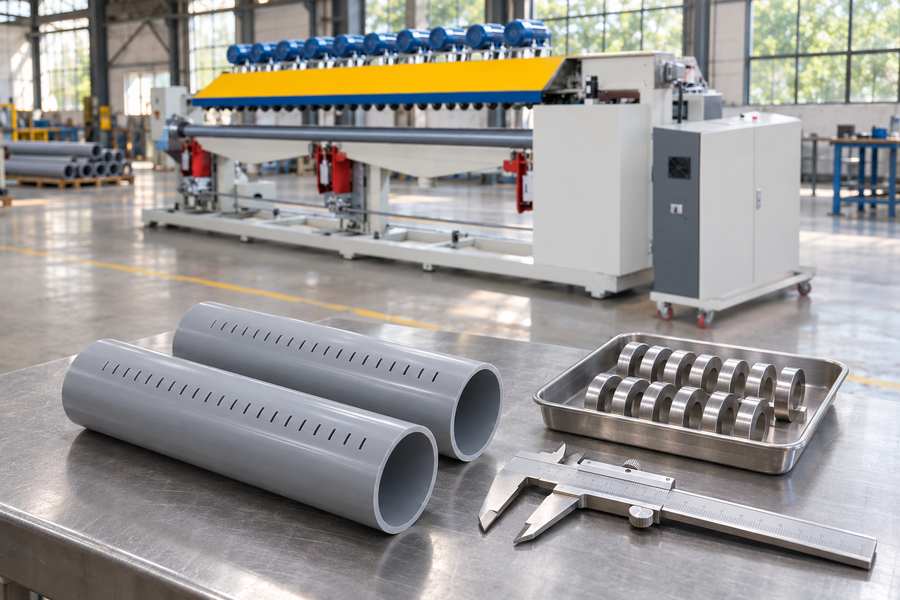
The trial record should identify relevant setup conditions. These may include blade arrangement, workpiece positioning, cutting settings, blade condition, and the specified clamping procedure.
Finished slot width must be measured independently of blade body thickness and nominal spacer dimensions. The measurement procedure should define whether the pipe is inspected before or after any specified deburring operation.
Slot center pitch should also be checked. Measuring only the distance between slot edges can conceal differences in individual slot widths and produce an incomplete assessment of the pattern.
For accurate comparison, use a consistent pipe reference and measurement orientation. Pipe ovality or local surface variation may affect measurement positioning, so the inspection fixture and reference method should be documented.
Where slots extend around the pipe circumference, the angular reference should be controlled. The inspection method must distinguish intentional slot orientation from variation introduced during workpiece positioning.
Finished-product inspection should cover both local and overall characteristics. Individual slot widths, adjacent center distances, axial positions, and end margins may require separate measurements.
Burrs and local deformation should be recorded according to the product drawing. A width measured across an unwanted burr may not represent the functional opening required by the application.
Measurement uncertainty also deserves consideration when results approach an acceptance boundary. Instrument resolution, fixture repeatability, operator technique, and surface condition can influence the reported value.
The acceptance procedure should establish how uncertainty is handled. Buyers and suppliers should agree on the decision rule before inspection rather than resolving borderline results after delivery.
Prepare the Purchase Specification and Supplier Acceptance Requirements
The purchase specification should convert engineering requirements into measurable component and assembly controls. It must provide enough information for the supplier to understand the intended blade arrangement without guessing the machine’s internal architecture.
A complete technical package also helps prevent disagreements about whether a tolerance applies to an individual spacer, an assembled blade position, or the finished pipe.
Prepare a Complete Technical Drawing and Specification
The drawing should identify nominal spacer thickness, permissible dimensional variation, and the locations used for inspection. State the blade plate dimension on its own drawing line and show exactly where its thickness is to be checked.
Blade center pitch should appear as an assembly requirement rather than being inferred from spacer dimensions alone. The first-blade datum and required final blade position should also be identified where applicable.
Spacer bore dimensions must correspond to the confirmed mounting interface. Include fit requirements, flatness, parallelism, and other geometric controls only where they influence assembly or functional performance.
The assembly drawing should show the complete blade and spacer sequence. It should identify combined spacer packs, shims, collars, locating components, and the direction of assembly.
Units and drawing revisions must remain consistent throughout the documentation. If a revised pipe drawing changes slot pitch or end distances, the tooling specification should be reviewed against the new requirements.
A useful specification should also separate nominal dimensions from acceptance limits. This prevents suppliers from interpreting a reference dimension as an independently controlled tolerance.
Define Inspection and Acceptance Requirements
Component inspection and assembled tooling inspection should have separate acceptance criteria. Passing an incoming spacer check leaves the assembled blade positions unproven; those positions need their own inspection.
For individual components, specify the required dimensional and geometric measurements. For the assembly, identify blade positions, adjacent center pitches, cumulative position, and total stack length where necessary.
The inspection plan should state the measurement equipment and conditions. Define instrument resolution, calibration expectations, measurement locations, and the required reporting format.
First-article inspection is particularly useful when a new blade arrangement or spacer specification is introduced. It allows the proposed dimensions and assembly method to be reviewed before routine production acceptance.
Subsequent sampling should reflect the dimensional risk and manufacturing process. Critical dimensions may justify more frequent inspection than characteristics with little influence on the finished slot pattern.
Nonconforming results also require an agreed procedure. Define how rejected components, dimensional deviations, rework, and proposed drawing changes are reviewed and approved.
Buyers should request supporting documentation that includes:
- Individual spacer and blade dimensional inspection records.
- Approved component and assembly drawings.
- Blade stack-up calculation and tolerance allocation.
- Relevant flatness, parallelism, and bore inspection results.
- Assembled blade position and runout measurements.
- Representative cutting trial records.
- Finished slot width and center pitch inspection results.
These documents provide traceability between component manufacturing, assembly accuracy, and finished pipe acceptance. They also establish a useful reference for replacement tooling and future specification revisions.
Confirm Requirements Against the Selected Machine
Tooling specifications must be reviewed against the actual machine configuration. Published workpiece dimensions provide useful selection information, but they do not establish the dimensional capabilities of every blade mounting arrangement.
For example, the DS250-SA pipe slotting machine has a published pipe diameter range of 75–250 mm and a pipe length range of 3–6 m.
These dimensions describe its published workpiece envelope. They should not be interpreted as evidence of particular spacer thickness tolerances, blade center pitch accuracy, or guaranteed finished-slot dimensions.
The available product information does not establish a specific blade count, spacer arrangement, arbor configuration, or clamping architecture. Buyers should therefore obtain confirmation before preparing detailed tooling drawings.
Yuyu Machinery should review the required blade arrangement against the selected machine’s actual mounting interfaces. This review should identify which dimensions are controlled by replaceable spacers and which depend on machine locating features.
The achievable inspection and acceptance requirements should also be discussed before production. If a buyer requires a specific cumulative blade-position limit, the supplier needs to understand the datum and measurement method used to verify it.
A quotation request should include the pipe drawing, nominal slot width, required center pitch, slot quantity, axial and circumferential positioning requirements, and representative material and wall thickness.
It should also identify the proposed blade arrangement, spacer dimensions, mounting interface information, critical tolerances, and required inspection records.
For the cutting trial, specify the workpiece dimensions, operating conditions to be recorded, measurement locations, and acceptance limits for finished slot width, center pitch, and overall slot position.