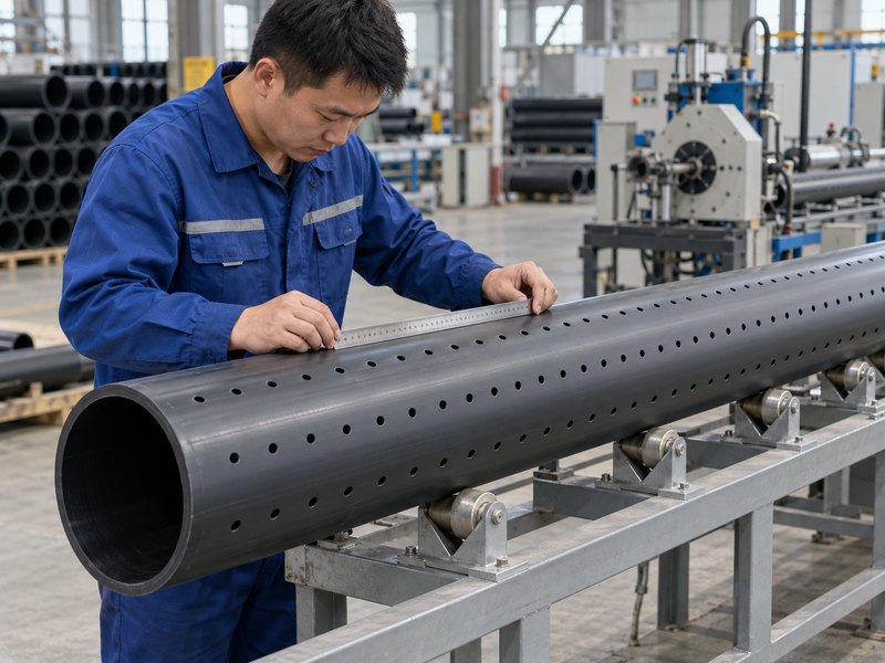
Inspect hole position by locating each hole center from a defined pipe-end reference and circumferential reference, then checking axial pitch, row angle, stagger offset, and accumulated deviation against the approved drawing. Support the pipe without distorting it, use a repeatable measuring setup, and inspect every row at several positions along the perforated length.
A neat-looking pattern can still be misplaced. Correct spacing between neighboring holes does not confirm the first-hole position, and correct spacing between rows does not confirm their orientation relative to the installation reference.
Define the Hole Pattern Before Selecting Inspection Tools
Turn the product drawing into a measurable inspection plan. “Four rows of evenly spaced holes” leaves too much open to interpretation.
| Drawing Item | What the Inspection Plan Must Define |
| Pipe reference | Which end establishes the axial origin; how the pipe axis is established |
| Angular origin | Approved longitudinal reference, installation mark, or datum feature |
| Row layout | Row count, angular positions, and direction of angle measurement |
| Axial pattern | First-hole center, center-to-center pitch, and final-hole position |
| Stagger | Specified axial offset between identified rows |
| Perforation limits | Start, finish, and unperforated connection zones |
| Acceptance | Applicable tolerances, measurement conditions, and decision rule |
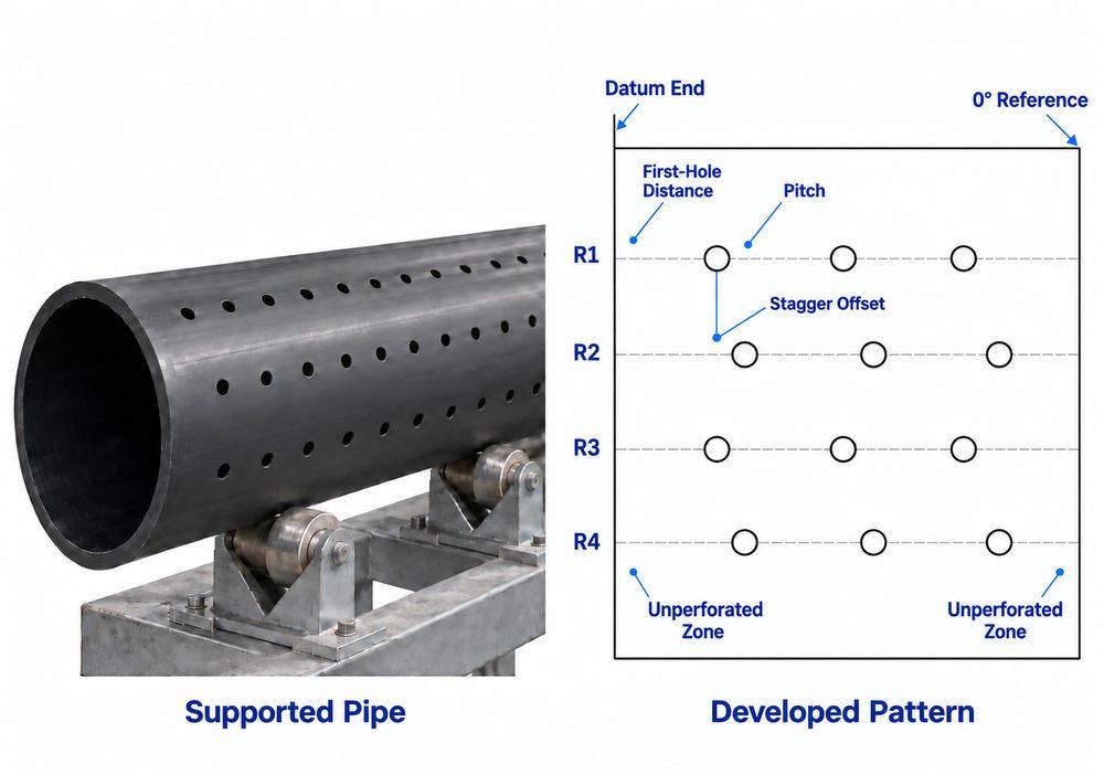
Yuyu’s DS400F pipe perforating machine product table lists parallel and staggered punching. Include the inspection drawing when requesting a configuration; a pattern description alone does not establish achievable accuracy.
Agree whether acceptance uses separate axial and angular limits or a drawing-defined geometric position tolerance. These require different evaluation methods. Do not invent a universal tolerance from pipe diameter or hole size.
Establish Repeatable Datums and Pipe Support
Long plastic pipes can sag, roll, or flatten under inspection loads. A measurement is only useful when the setup reproduces the agreed reference system.
- Clean the reference end and inspection surfaces; remove loose chips without altering hole edges.
- Check end condition, straightness, and ovality before locating the pattern.
- Position the pipe on aligned saddles or rollers that limit sag without forcing it straight.
- Locate the approved axial reference against a suitable stop.
- Establish the angular origin independently of the holes being inspected.
- Restrain rolling with light, repeatable contact; avoid squeezing the wall.
If the end is angled or damaged, do not select a convenient high point as zero. Use the drawing’s reference method or agree a revised method before inspection.
For custom perforating support and clamping requirements, provide actual outside diameter, wall thickness, length, material, and expected ovality. Confirm the proposed arrangement on representative pipes.
Do not assume a printed stripe is an angular datum unless the drawing assigns that function and its location is controlled. Record pipe temperature and conditioning where dimensional sensitivity matters.
Measure Axial Pitch and Absolute Hole Positions
Measure hole centers along the established pipe-axis direction. A tape following a bowed surface can produce a different result from an axial measurement.
| Check | Method | What It Reveals |
| First-hole distance | Reference end to first center in each row | Initial positioning error |
| Local pitch | Consecutive centers within one row | Feed-step variation |
| Cumulative position | Reference end to selected later centers | Accumulated feed error |
| Final-hole location | Reference end to last center | Pattern length and end-zone compliance |
For a uniform-pitch row, expected position is xₙ = x₁ + (n − 1)p, where x₁ is the specified first-hole position and p is nominal pitch.
For example, x₁ = 100 mm and p = 50 mm place hole 21 at 1,100 mm. An actual position of 1,103 mm gives +3 mm cumulative deviation; acceptance still depends on the drawing.
Measure from the common origin rather than repeatedly moving the ruler from hole to hole. Retain local-pitch readings as well: endpoint measurements can conceal alternating long and short steps.
Before ordering a DS400F configuration for the required hole layout, request a trial report covering both short-range pitch and full-length position under the proposed production conditions.
Check Row Angles and Stagger Offsets Separately
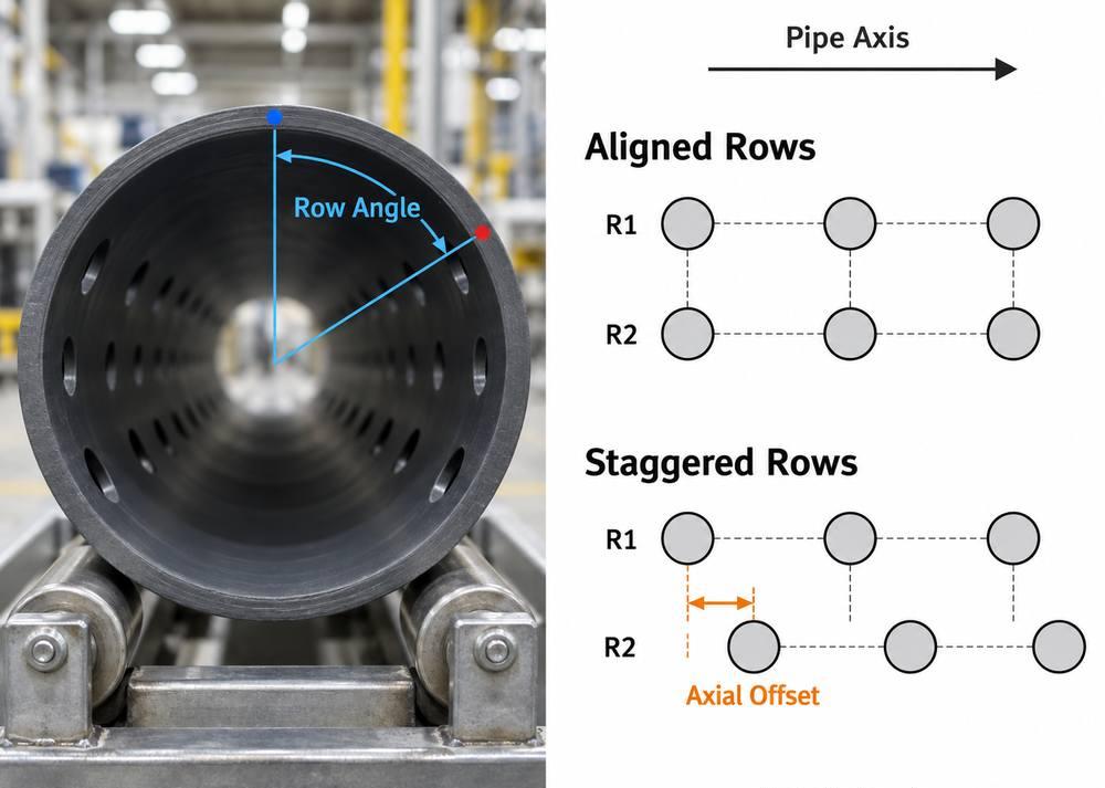
Row angle locates a row around the circumference. Stagger locates one row’s holes axially relative to another. Each check must be passed independently.
Check Angular Position at Multiple Locations Along The Pipe
- Use a centered rotary fixture, a validated optical arrangement, or an appropriate coordinate measurement setup.
- Measure each row relative to the independent angular origin.
- Repeat near the beginning, middle, and end to detect row drift or pipe rotation.
- Check adjacent row spacing and absolute row orientation where both are specified.
A flexible wrap template can screen a pattern, but its seam alignment, stretch, and diameter fit must be controlled. On a round section, θ = 360s/C converts circumferential arc distance s to degrees using circumference C.
That relationship assumes a circular section and an arc measurement. A straight caliper distance across the pipe is a chord, and ovality limits simple angle conversion.
Compare Corresponding Holes for Stagger
Identify the intended hole pairs on the drawing, then subtract their measured axial coordinates. Do not assume every staggered pattern uses half-pitch offset; Yuyu’s hole-pattern overview describes several layout options, while the approved drawing must define the actual offset.
Locate Hole Centers Without Letting Burrs Bias the Result
Hole-position inspection becomes unreliable when different inspectors select different edges. Specify whether the measured feature is the outer opening, inner opening, or a hole axis established through the wall.
| Method | Suitable Use | Limitation to Control |
| Calipers and scale | Accessible holes with moderate requirements | Edge selection, curvature, and alignment |
| Fitted pins or center plugs | Repeatable round openings | Clearance, taper, and wall deformation |
| Dedicated template | Fast checks of a repeated pattern | Datum seating, wear, and limited numerical data |
| Vision measurement | Documented center coordinates | Lighting, lens calibration, curvature, and edge-fitting rules |
| Coordinate measurement | Detailed three-dimensional verification | Pipe support, accessibility, and measurement uncertainty |
A loose pin can tilt; an oversized plug can deform a thin wall. Neither reliably establishes the center. For irregular openings, use a documented fitting method and inspect hole shape separately.
A fixed-camera side photograph cannot directly establish all circumferential positions. Use calibrated views or controlled rotation, and check the method against independently measured samples.
Inspect Every Row Across the Full Perforated Length
First-article inspection should cover the complete pattern definition. Routine inspection can use an agreed sampling plan based on product risk, process stability, batch size, and customer requirements.
| Inspection Point | Checks to Include |
| First piece after setup | Every row, reference orientation, first holes, pitch, stagger, end zones |
| Beginning, middle, and end | Axial position and row angle in each row |
| Tool or recipe change | Affected dimensions plus checks that the complete pattern remains correct |
| Restart after interruption | New start position and continuity of the pattern |
| Routine production interval | Defined sample quantities and locations, with recorded trends |
Pay particular attention to transitions between feed strokes or clamping stages. Measuring only at the pipe ends may fail to detect a localized shift in that area.
For corrugated pipes, also verify the specified crest or valley location. Record the profile reference used; a smooth-wall wrap template may not seat reliably on corrugations.
Read the Error Pattern Before Adjusting the Machine
Use measurements to narrow the investigation. Similar defects can have different causes, so verify the suspected mechanism before changing settings.
| Observed Pattern | Checks to Prioritize |
| All holes shifted axially by a similar amount | End stop, recipe origin, reference-end consistency |
| Deviation increases with hole number | Feed calibration, roller slip, thermal condition |
| Row angle changes along the length | Pipe rolling, torsion, restraint, support alignment |
| One row differs from the others | Individual head location, tooling alignment, row-specific recipe |
| Repeated step change | Regripping, feed-stage transition, synchronization |
| Results change between inspectors | Datum seating, center definition, fixture force, instrument method |
Adjust one confirmed factor at a time, recording measurements before and after each change. Re-zeroing a program can hide an offset while leaving slip or accumulated feed error unresolved.
Record Results and Control Nonconforming Pipes
Use one record that connects the physical pipe, machine settings, and inspection outcome.
- Identity:order, batch, pipe ID, drawing revision, material, and dimensions.
- Setup:machine recipe, tooling identification, supports, and relevant temperature.
- Location:row number, hole number, nominal coordinates, measured coordinates, and deviation.
- Measurement:instrument ID, method, inspector, and date.
- Decision:applicable limits, pass/fail status, and disposition.
For results near a limit, apply the agreed decision rule with measurement uncertainty considered. Repeat an unstable measurement using a verified setup before deciding disposition.
If a hole is outside tolerance, identify and segregate affected pipes, establish the potentially affected production interval, and correct the verified cause. Release restarted production only after the required reinspection.
Do not enlarge a misplaced hole or add another hole without approved repair criteria. Either action can change open area, remaining material between holes, and product performance.
Specify a Machine Trial That Demonstrates Inspectable Accuracy
Give the supplier the same drawing and inspection method that production will use. A useful acceptance trial should include:
- Representative pipe sizes, materials, wall thicknesses, and lengths.
- The most demanding row count, pitch, stagger, and unperforated zones.
- Agreed production speed and normal handling conditions.
- Full-length results from every row on the agreed sample quantity.
- A changeover and restart check where relevant.
- A retained approved sample and signed measurement report.
The purchase specification should connect the hole pattern to measurable acceptance limits. That makes first-article approval, routine inspection, and supplier acceptance consistent—and gives operators usable evidence when the pattern begins to drift.