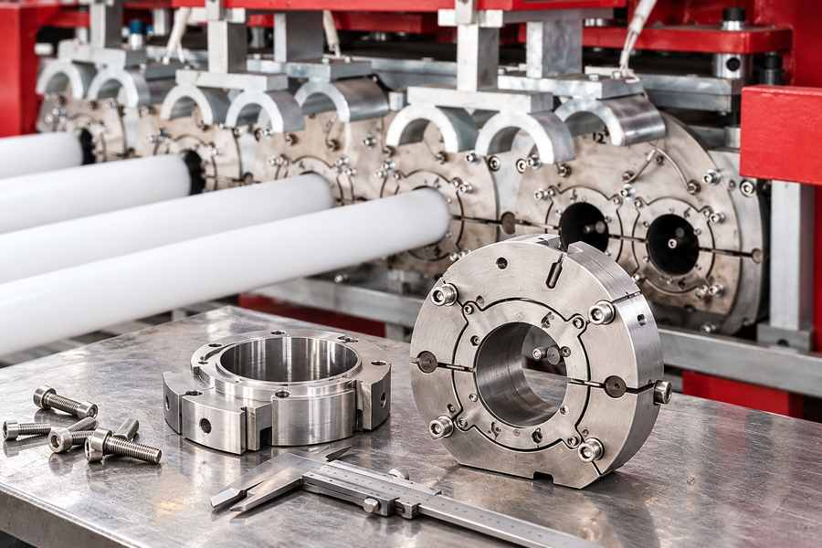
Tool-mounting interfaces determine whether a mandrel, mold, or adapter fits a custom belling machine and stays aligned through forming and withdrawal. Matching bolt holes alone does not establish compatibility.
Buyers need dimensioned drawings, agreed reference points, and recorded installation tests before accepting a tooling arrangement. The following seven checks connect mounting details with observable faults and measurable acceptance evidence.
1. Mounting Face Geometry and Reference Datums
Define the Mounting Surface and the Tool Being Mounted
Start by identifying each assembly that actually attaches to the machine. An internal mandrel, external mold, and intermediate adapter may use different carriers and independent interfaces.
Ask for an assembly view showing those connections separately. A statement that the machine accepts custom molds does not identify which existing parts can be retained when tooling changes.
For each mounting face, record usable contact width and height, recesses, shoulders, relief areas, and the direction from which the tool approaches its seat. Include obstacles near the face.
Dimensions must refer to physical features, not the approximate outline of a casting or plate. The usable contact surface can be smaller than the carrier’s overall dimensions.
Establish Datums That Can Be Inspected
A primary datum plane defines where the mounted tool seats. A second reference establishes lateral position; an axial origin connects the mount to the forming station.
The interface drawing needs a coordinate direction and a clear distinction between nominal dimensions and inspection requirements. Applicable flatness and perpendicularity limits belong on the agreed drawing, not in an informal email.
Use the following schedule when reviewing the quoted interface drawing. The measurement method and permissible deviation remain project-specific and must be approved before manufacture.
| Drawing Item | Definition to Agree | Evidence to Retain |
| Primary mounting plane | Exact contact surfaces establishing the seated position | Marked drawing and surface inspection record |
| Tool axis reference | Axis used to dimension the tool relative to pipe clamping | Datum diagram and axis measurement points |
| Axial zero position | Plane from which projection and working depth are measured | Signed dimensioned assembly view |
| Contact geometry | Usable lands, recesses, shoulders, and reliefs | As-built dimensional inspection |
| Geometric controls | Relevant flatness, squareness, and datum-related limits | Results against approved drawing limits |
A tool that rocks on its seat, leaves a measurable contact gap, or requires unplanned shimming warrants investigation before a forming trial. Tightening fasteners may conceal the original seating problem.
2. Tool-Centering and Positive Locating Features
Separate Accurate Location from Bolt Clamping
A bolt pattern connects components, but clearance around bolts may allow relative movement. Confirm whether the quoted design uses pilot registers, dowels, shoulders, keys, or another positive locating arrangement.
For a pilot, request both mating diameters, engagement length, lead-in details, and fit requirements. For pins or keys, request positions, sizes, engagement, and provisions for removal.
The drawing must show which features establish the working position and which merely retain the assembly. Otherwise, separate workshops may manufacture individually plausible parts that cannot locate consistently together.
This matters especially when a tool is removed for maintenance or a different socket profile. A system that aligns only through repeated manual adjustment may not meet the buyer’s changeover expectations.
Where several forming stations share a carrier, establish whether locating references are common or station-specific. Transferring nominal center distances without checking actual clamp axes can reproduce an alignment error across tools.
Measure the Working Axis Under a Defined Setup
Agree on how the tool axis will be compared with the pipe-clamping reference. Identify measurement stations along the tool, the instrument used, and the assembled condition during inspection.
Checking one point alone can miss angular misalignment. Where relevant, compare readings at separated axial positions, and record the tool orientation so measurements can be repeated.
The measured relationship should be checked against the agreed acceptance limits, allowing for measurement uncertainty. A visually centered mandrel is not a substitute for a recorded result.
Uneven socket walls, localized rubbing, or repeat adjustments after installation are useful clues. However, heating variation and pipe positioning can produce similar symptoms, so confirm the mounting geometry first.
3. Mounting Bolt Pattern and Fastener Engagement
Specify the Complete Fastening Arrangement
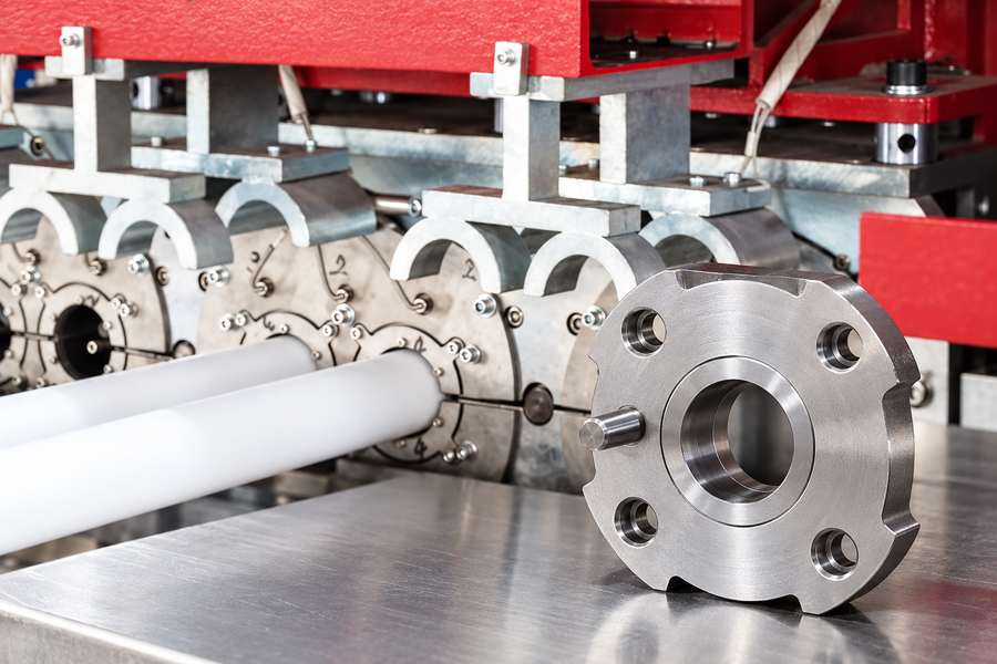
A usable bolt-pattern drawing identifies hole count, coordinates or pitch circle, orientation, thread designation, and the relationship of every hole to the established datums.
A symmetrical pattern can still be interpreted from the wrong viewing direction. Add an unmistakable orientation reference so the buyer and toolmaker use the same coordinate system.
For tapped holes, confirm the usable thread engagement rather than relying on total drilled depth. Check the bolt stack-up, including tool plate, any adapter, washers, and counterbores.
Fastener material, tightening method, and any required locking provisions are matters for the quoted joint design. Do not substitute a generic torque value without considering the specified fastener and seating arrangement.
Access belongs in the interface review. A bolt that fits on the drawing may remain unreachable behind a clamp, guard, hose, or adjacent mold component when the assembly is installed.
Inspect the Joint After Assembly
During a fit-up trial, verify that fasteners enter without forcing the tool sideways. Confirm complete seating before tightening, then document the specified tightening sequence and inspection results.
Distinguish clamping from resistance to operational shear. Where the design depends on friction or mechanical stops, obtain the intended load path rather than assuming bolt shanks act as dowels.
Mismatched holes, damaged threads, persistent joint gaps, or recurring loosening are reasons to stop and identify the cause. Enlarging holes on site changes the approved interface and may reduce repeatability.
Keep the final bolt schedule with the tool drawing. It gives maintenance personnel a reference when an adapter or replacement assembly arrives later.
4. Tool Projection, Axial Offset, and Movement Clearance
Measure Projection from the Approved Mounting Datum
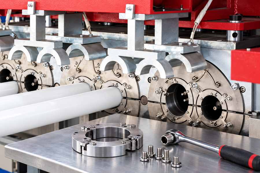
Tool projection is the axial distance from the seated mounting reference to a defined working feature, such as the mandrel shoulder or designated forming surface. Specify that feature explicitly.
An overall tool length is not equivalent to working projection. Adapters, locating shoulders, and inserted portions change the installed position even when two tools have similar outside dimensions.
Request an assembly drawing that includes the tool, mount, pipe clamp, and relevant forming components in their working relationship. Yuyu Machinery describes the positioning, clamping, heating, forming, cooling, and release stages in its belling machine overview; the purchased configuration still needs its own dimensional verification.
When several tools are quoted, compare their projections from the same datum. A tool-specific offset table is more reliable than a handwritten adjustment beside each tooling drawing.
Check Clearance Throughout Movement
Review the approach, forming, withdrawal, and removal positions relevant to the machine. Check the tool’s complete envelope, including fastener heads, adapters, utility fittings, and lifting features.
For segmented external molds, evaluate clearance with sections open as well as closed. An adapter that fits during a stationary check may obstruct a moving clamp or opening mechanism.
A cylinder’s nominal stroke does not establish usable tooling clearance. The installed tool and surrounding equipment determine whether a required position can be reached without interference.
For acceptance, record the positions checked and how clearance was established. A witnessed dry movement test can reveal obstructions that a two-dimensional drawing does not make obvious.
Scrape marks, a tool that cannot withdraw cleanly, or unexpected socket-depth corrections may indicate interface offsets. Also examine tooling shape and process settings before assigning the fault.
5. Tool Weight, Overhang, and Mounting Joint Rigidity
Identify Loads Acting Through the Interface
Obtain the complete installed tooling mass, not only the bare mold or mandrel weight. Include adapters, connection blocks, and other parts supported by the same mounting arrangement.
Record the center-of-gravity location relative to the mounting plane. An overhung tool places a bending moment on the carrier even before forming forces or motion-related loads are considered.
Hypothetical screening calculation: A 40 kg tool with its center of gravity 0.20 m horizontally from the mounting plane creates approximately 78 N·m of static gravitational moment (40 × 9.81 × 0.20). This excludes forming and dynamic loads and is not a mounting-capacity rating.
The actual assessment also depends on tool orientation, force direction, carrier stiffness, and the arrangement of contact and locating surfaces. Request the relevant design basis for the quoted assembly.
Define How Joint Movement Will Be Assessed
Determine whether the tool is expected to remain in one position or move during forming. Agree on measurement locations and representative operating conditions for any rigidity assessment.
A displacement reading taken on the machine frame does not necessarily describe movement at the tool working end. Separate carrier deformation, joint movement, and tool deflection where practical.
Readings taken only after the machine stops may miss temporary displacement during insertion. Where practical, observe the relevant load stage using an approved measurement arrangement that does not compromise machine safeguards.
Check for changes between unloaded and loaded positions and for residual shifts after loading is removed. Record instrument locations, readings, and relevant process conditions alongside the results.
Changing alignment under force, witness marks at the joint, and unusual locating-surface wear can indicate a structural concern. Do not adopt a universal allowable deflection; specify what the particular socket process requires.
6. Tool-Mounted Utility Connections and Interface Clearance
Document Connections That Cross the Mounting Boundary
Some quoted tooling arrangements may require cooling water, pneumatic services, electrical connections, or sensing interfaces at the tool. Others will use none of these connections across the mount.
For each applicable service, specify port or connector location, identification, mating type, sealing arrangement, and direction of connection. These details belong on the assembly drawing or a referenced connection schedule.
A connection map can pair every labeled tool port with its matching machine-side service. Incorrect hose routing or undocumented sensor assignments can resemble process faults even when the mechanical mount is correctly assembled.
Clarify which connections remain on the machine and which are disconnected during a tool change. This affects fitting accessibility and the space needed to remove the complete tool.
A hose may fit at the installation position but contact a moving component during withdrawal. Check routing through the relevant motion envelope, including permitted bends and restraint points.
Inspect Access, Leaks, and Movement Interference
Use a connection check appropriate to the fitted utility. Record observations at the specified operating condition; do not apply a generic pressure or electrical test to every interface.
During the movement check, look for twisted hoses, pinched cables, fitting contact, or connectors blocked by a fastener. Confirm that identification remains readable after installation.
Leaks, intermittent signals, or damaged cable jackets can have several causes. Record the location and operating position where each symptom appears before changing components.
Purchasing records should make clear whether special fittings, quick-disconnects, or carrier-mounted brackets are included in the quote. Their presence cannot be assumed from general customization language.
7. Tool Changeover Access and Remounting Repeatability
Verify the Actual Removal and Installation Path
Interchangeability means more than matching a mounting drawing. Confirm the space needed to disengage locating features, extract the tool, reach fasteners, and use any specified lifting arrangement.
Check whether changing between socket profiles requires a new adapter, carrier adjustment, or different service connections. Obtain a compatibility list identifying which assemblies use the approved interface unchanged.
Request a documented installation sequence covering seating surfaces, locating engagement, fastener installation, utility reconnection where applicable, and alignment verification. This is a proposed acceptance requirement, not an assertion about standard equipment.
A physically inaccessible fastener or tool that binds during withdrawal can turn an apparently simple replacement into a larger machine intervention. Demonstrate removal access with the quoted arrangement.
Test Remounting Repeatability and Retain Acceptance Evidence
Agree on a defined number of removal-and-reinstallation repetitions and measure the same tool references each time. Record any shimming, adjustment, or part replacement made between readings.
Repeatability is the spread of positions obtained under the specified procedure; it is not the same as initial alignment accuracy. Define the calculation or reporting method before accepting the test.
Where sample socket inspection forms part of acceptance, identify the pipe material, size, tooling configuration, relevant process settings, and drawing-defined product dimensions. A satisfactory sample alone cannot prove every mounting detail.
| Acceptance Activity | Record or Observation | Acceptance Basis to Agree |
| Mounting-face inspection | Contact dimensions, datums, surface condition | Approved interface drawing |
| Locating and axis check | Mating-feature measurements; tool-to-clamp relationship | Specified datum scheme and alignment limits |
| Fastener installation | Hole fit, seating condition, engagement, tightening record | Approved joint and installation documents |
| Installed movement check | Positions tested, minimum observed clearances, interference findings | Agreed working and removal envelopes |
| Loaded-position review | Tool-end and joint readings under stated conditions | Configuration-specific movement criteria |
| Utility check, if fitted | Connection identification, access, leakage or signal observations | Approved connection schedule and test method |
| Reinstallation trial | Positional readings and adjustments for each remount | Agreed repetition count and repeatability limits |
Ask Yuyu Machinery to clarify inspection responsibilities, drawing revisions, and the form of records available through its service and technical consultation discussion before purchase approval.
The purchase agreement can then identify which tests occur before shipment and which require the complete installed line. Keep unresolved deviations linked to drawing revisions rather than accepting verbal corrections.
Finally, retain the signed drawings, measurement sheets, assembly instructions, and sample inspection records together. They provide a baseline for future tool purchases, replacement parts, and troubleshooting without treating an untested interface as interchangeable.