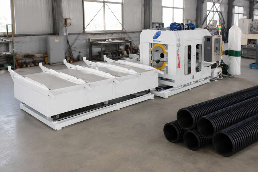
A pipe threading tool usually needs replacement when thread surfaces become rough, dimensions drift, cutting temperature rises, chip shape changes, or machine load increases. These signs should be evaluated together rather than judged from one defective pipe.
Early Signs of Threading Tool Wear
| Warning Sign | What Operators May Notice | Main Risk |
| Rough thread surfaces | Torn edges, ridges, or uneven grooves | Poor connection quality |
| Unstable thread dimensions | Changes in depth, pitch, or profile | Assembly problems |
| Higher cutting temperature | Softened plastic or melted edges | Pipe surface damage |
| Abnormal chips | Dust, strings, or chips stuck to the tool | Cutting-zone blockage |
| Increased machine load | Vibration, noise, or longer cycles | Tool and spindle damage |
Several warning signs may appear at the same time during pipe threading machine operation. A rough thread combined with rising cutting temperature is usually a stronger replacement signal than an isolated surface defect.
1. Thread Surfaces Become Rough
A sharp tool removes plastic material cleanly and leaves a defined thread profile. As the cutting edge wears, it may press, tear, or drag the material instead of cutting it smoothly.
Common surface changes include:
- Fuzzy thread edges
- Torn grooves
- Uneven ridges
- Smeared plastic
- Small burrs
- Inconsistent surface gloss
Surface quality should be inspected at the thread entry, middle section, and final cutting position. Wear may first appear where the tool enters or exits the plastic pipe.
Adjusting the feed speed may temporarily improve the finish, but repeated adjustment is not a permanent solution. When a previously stable recipe begins producing rough threads, the tool condition should be checked before changing other machine parameters.
2. Thread Dimensions Start Drifting
Tool wear can gradually change the effective cutting shape. The thread may become too shallow, too narrow, or less defined even though the Pipe Threading Machine continues following the same programmed path.
Operators should monitor:
- Thread depth
- Thread pitch
- Crest width
- Root shape
- Thread length
- Connection fit
Dimensional drift often develops slowly across several production cycles. Measuring only the first pipe in a batch may miss changes that appear after the cutter reaches its normal operating temperature.
A worn tool may also produce different results around the pipe circumference. If clamping and positioning remain stable but thread dimensions continue changing, cutter wear is a likely cause.
3. Cutting Temperature Keeps Rising
Threading creates friction between the tool and the plastic pipe. A sharp cutting edge removes material efficiently, while a worn edge creates more rubbing and heat.
Excessive temperature may cause:
- Melted thread edges
- Plastic sticking to the cutter
- Discoloration around the thread
- Softened thread crests
- Unusual surface shine
- Dimensional change after cooling
Dry cutting systems may show heat-related problems earlier because they rely on tool geometry, airflow, and cutting parameters. Cooled cutting can control temperature for longer, but cooling should not be used to hide a severely worn tool.
Operators may reduce spindle speed or feed rate to control heat. When the same plastic pipe previously ran well at higher settings, repeated speed reductions often indicate that the cutter is losing sharpness.
4. Chip Shape Changes
Chip appearance provides a useful indication of how the tool interacts with the plastic pipe. A stable threading process normally produces a predictable chip shape when the material and processing recipe remain unchanged.
Tool wear may change the chips into:
- Fine powder
- Long string-like pieces
- Thick irregular curls
- Melted particles
- Chips attached to the thread
- Material wrapped around the cutter
Different plastic formulations naturally produce different chips, so comparisons should use the same pipe material and specification. A sudden change after a stable production period is more meaningful than differences between unrelated plastic materials.
Poor chip removal can create similar symptoms. The extraction system, air nozzle, and cutting area should be cleaned before confirming that the tool requires replacement.
5. Machine Load and Vibration Increase
A dull tool requires more force to remove the same amount of plastic. The machine may show higher spindle load, stronger vibration, abnormal sound, or slower cutting movement.
Typical changes include:
- Rising motor-load readings
- Increased cutting noise
- Tool chatter
- Pipe movement inside the clamp
- Longer cycle time
- Frequent machine alarms
Vibration can damage the thread surface and reduce dimensional consistency. It may also accelerate wear on the spindle, tool holder, clamps, and supporting guides.
Machine load should be compared under the same pipe diameter, wall thickness, thread profile, and cutting speed. A higher load after switching to a thicker plastic pipe does not automatically indicate tool failure.
How to Confirm Tool Wear
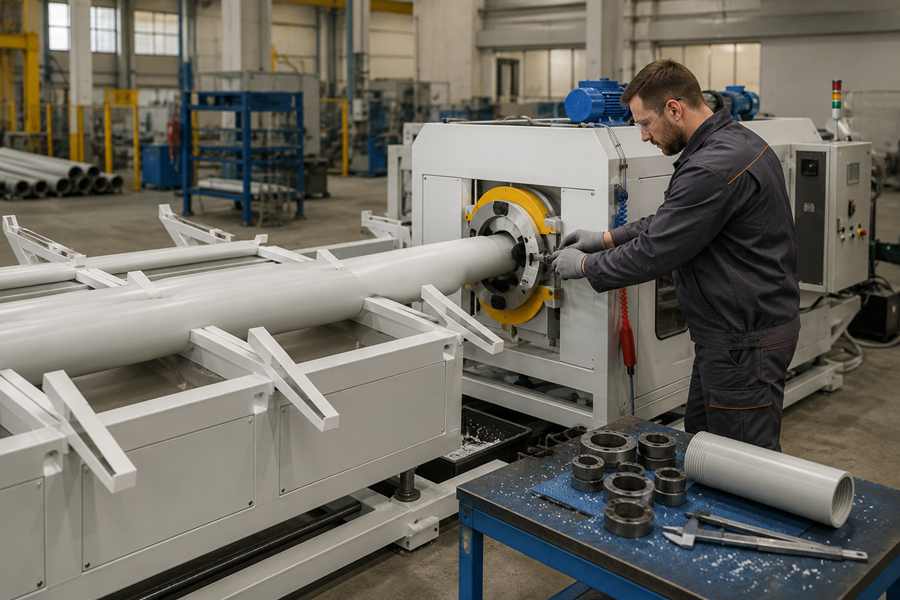
Not every threading defect is caused by cutter wear. Incorrect clamping, pipe variation, chip buildup, tool misalignment, and unsuitable cutting parameters can create similar results.
| Observed Problem | Check Before Replacing the Tool |
| Thread depth varies | Pipe positioning, clamp stability, and tool runout |
| Finished surface becomes uneven | Check chip evacuation, cutter speed, and feed settings |
| Plastic melts | Cooling flow, airflow, and cutter temperature |
| Thread is off-center | Pipe roundness, guides, and clamping position |
| Vibration increases | Tool holder, spindle, supports, and loose fasteners |
A practical inspection sequence is:
- Clean the tool and cutting area.
- Check the tool holder and spindle connection.
- Confirm pipe positioning and clamping.
- Review speed, feed, and cooling settings.
- Process another pipe using the same specification.
- Replace the tool if the defects remain.
This sequence avoids unnecessary replacement when the actual problem comes from machine setup. It also prevents operators from repeatedly changing a stable recipe to compensate for a worn cutting edge.
Replace, Resharpen, or Adjust?
Some threading tools can be resharpened, while others are designed for direct replacement. The decision depends on the tool structure, remaining cutting material, required thread accuracy, and available sharpening equipment.
Resharpening should restore:
- Cutting-edge geometry
- Tool diameter
- Thread profile
- Clearance angle
- Surface condition
- Tool balance
An incorrectly sharpened tool may appear sharp but produce the wrong thread dimensions. For precise plastic pipe threads, replacement is often safer when the original tool profile cannot be restored accurately.
Parameter adjustment is suitable only when the tool remains in acceptable condition. Repeatedly increasing cutting pressure or lowering speed may extend operation briefly, but it can also raise cycle time and rejection risk.
Set a Practical Replacement Standard
Tool replacement should not rely only on a fixed number of processed pipes. Plastic formulation, wall thickness, thread depth, cutting method, and production duration can all affect tool life.
A useful tool record should include:
- Tool installation date
- Plastic pipe specification
- Number of processed pipes
- Total cutting time
- Thread inspection results
- Tool cleaning frequency
- Replacement reason
Recording the reason for each replacement helps separate normal wear from damage caused by incorrect setup. It also supports more accurate spare-tool planning.
The most useful replacement limit is the point where thread quality or process stability begins to decline. Waiting until the tool breaks may damage the plastic pipe, holder, or spindle and create a longer production interruption.