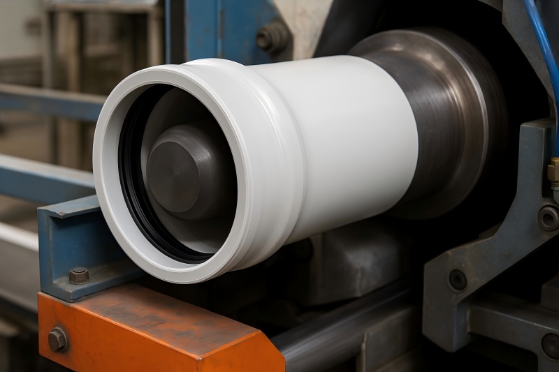
In pressure and gravity networks alike—potable water, wastewater, storm drains, vent stacks—the joint is the first line of defense against infiltration, exfiltration, and root intrusion. Modern thermoplastic pipes (PVC, CPVC, PP, PE) rely on a precisely formed socket—commonly called a “bell”—mated with a prepared spigot end, often with a factory-installed elastomeric sealing ring.
Achieving durable, leak-tight joints at scale is only possible because belling machines take a raw pipe end and transform it—under controlled heat, pressure, geometry, and cooling—into a standardized, repeatable sealing interface.
What “Leak-Proof” Really Means for Plastic Pipe Joints
“Leak-proof” is not just “no water dripping.” In plumbing and drainage systems, joints must resist:
- Internal pressure or head (positive pressure in supply lines; hydrostatic head in gravity mains during surcharge).
- Vacuum/negative pressure (transient events in drainage stacks).
- Groundwater infiltration (in sewers or storm drains).
- Soil movement and thermal cycling (expansion/contraction, minor deflections).
- Chemical exposure (household chemicals in drainage, disinfectants in potable water).
- Root intrusion (especially in buried sewer laterals).
A properly belled socket provides two cooperative defenses:
- Geometric interlock—a controlled socket profile that positions and retains the spigot.
- Elastomeric sealing—a compressed O-ring or integrated lip gasket creating radial contact pressure around the spigot’s circumference.
The Sealing Mechanism: Geometry + Materials
Socket Geometry
The bell’s internal profile typically includes:
- Lead-in taper to help alignment and reduce gasket roll.
- Seal groove/pocket with a controlled diameter and depth to position the gasket.
- Stop shoulder that provides an insertion limit and maintains gasket compression at design depth.
- Expansion/retention zone that prevents gasket displacement during insertion.
Elastomeric Gaskets
Common compounds (selected for temperature, fluid, and aging behavior):
EPDM: hot water and many chemicals; widely used for potable and drainage.
NBR (Nitrile): oil and fuel resistance for industrial lines and traps.
SBR: economical choice for many drainage applications.
Designs vary—circular O-ring, lip gasket, Rieber-style integrated gasket (mechanically locked into the socket during forming). The gasket’s role is to maintain radial sealing pressure despite deflection and dimensional tolerances. Typical design compression is often in the 10–30% range of the gasket cross-section, enough to seal but not so high that insertion force becomes excessive.
Spigot Preparation
A chamfered spigot (e.g., 15–30° chamfer with a controlled land) protects the gasket and eases insertion. The spigot OD tolerances and surface finish help the gasket slide rather than snag, minimizing the risk of gasket roll or nicks.
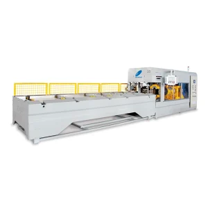
Inside the Belling Machine: How Leak-Tight Sockets Are Made
Belling machines convert a cut pipe end into its final sealing interface through four phases:
Heating
- Objective: Soften the thermoplastic at the end of the pipe to its forming window without degrading the material.
- Methods: Hot air convection, infrared (IR) heating, or contact heating tools.
- Controls: Independent temperature zones, pyrometers/IR sensors, part-present sensors, and timers. Good machines maintain uniform circumferential temperature to avoid ovality and wall thinning.
Forming & Gasket Integration
A calibrated mandrel (forming tool) with the final socket profile enters the softened pipe end.
Vacuum calibration and/or external clamps draw the pipe onto the mandrel, ensuring wall conformity and uniform thickness.
For integrated gasket sockets (e.g., Rieber style), the gasket is placed on the mandrel in a designated groove. During forming, the pipe material flows around and mechanically locks the gasket into the bell pocket—preventing displacement during installation and service.
Axial positioning and servo-controlled strokes ensure repeatable socket depth, groove dimensions, and shoulder location.
Cooling & Stabilization
Internal air or water cooling circuits on the mandrel, combined with external sprays or air knives, bring the bell below its softening point while held in shape.
Controlled cooling reduces residual stresses and preserves roundness (ovality), which is critical for uniform gasket compression.
Extraction & Inline Checks
The mandrel retracts, and the belled pipe moves to inline inspection: dimensional gauges, vision systems for gasket presence/orientation, and sometimes leak or vacuum checks at the socket level before bundling.
Why Belling Drives Leak-Tightness: The Engineering Controls
Belling machines deliver leak-proof performance because they bring process control to every variable that affects sealing:
Dimensional fidelity: Mandrels and calibrators replicate standard-compliant geometry (e.g., typical industry norms for sewer/drainage and water supply). Tight control of socket ID, groove depth, shoulder position, and taper ensures the right gasket compression.
Wall thickness management: Vacuum forming prevents thinning at bends or tapers, protecting long-term strength around the seal.
Roundness (low ovality): Uniform heating and symmetric forming minimize ovality. An out-of-round socket creates localized under-compression (leak risk) and over-compression (damage risk).
Gasket retention: Mechanical locking or friction-fit pockets avoid gasket displacement and roll-out during field assembly.
Surface quality: Smoothly formed interior surfaces prevent micro-leaks and abrasion of gasket lips.
Repeatability: Recipe-driven CNC/servo controls, auto-lubrication, and SPC integration keep every socket within tolerance—vital for large production runs.
Tolerances That Matter for Sealing
While exact numbers follow product standards and customer specifications, belling shops typically watch:
- Socket ID at seal zone: to achieve target gasket compression.
- Groove depth & width: to hold the gasket geometry without excess play.
- Socket depth & shoulder location: to ensure spigot insertion marks align and stop correctly.
- Ovality: commonly held to a small fraction of the diameter class; lower is always better for sealing.
- Wall thickness in the bell: to avoid weak spots that can creep or deform.
- Gasket seating: 360° seating with no twist, waves, or gaps.
Quality Assurance: How Plants Verify Leak-Proof Joints
A robust QA program confirms that the machine’s forming controls translate into sealing performance.
Dimensional & Visual Checks
- Go/No-Go gauges, internal comparators, and coordinate fixtures for socket ID, depth, groove.
- Vision systems verify gasket presence, orientation, and cleanliness.
- Spigot chamfer inspection to ensure field assembly won’t injure the gasket.
Hydrostatic & Vacuum Tests
- Hydrostatic (positive pressure): Socketed samples are assembled with a reference spigot and pressurized for a set duration; no leakage permitted.
- Vacuum (negative pressure): Especially for drainage, vacuum tests reveal micro-pathways where gaskets under-compress.
- Head tests for gravity pipe: Columns or sealed rigs simulate groundwater infiltration pressure.
Deflection & Shear Tests
- Joints are deflected by a specified angle to simulate installation misalignment; the joint must remain tight.
- Shear/earth load simulations assess tolerance to minor settlement.
Aging/Conditioning
Thermal cycling and chemical exposure protocols for elastomer and plastic ensure long-term sealing integrity.
Example QA Matrix (illustrative)
| Test Type | Purpose | Typical Criterion | Frequency |
| Socket Dimensions | Verify geometry for proper compression | Within drawing/spec tolerances | Hourly or per lot |
| Gasket Presence/Lock | Ensure correct seating & retention | 100% pass via vision or poke-yoke | 100% inline |
| Hydrostatic Pressure | Positive pressure tightness | No visible leakage over set time | Per shift / per size |
| Vacuum Tightness | Negative pressure performance | No bubbles/leak at specified vacuum | Per shift / per size |
| Deflection Tightness | Misalignment tolerance | Leak-free at X° deflection | Per lot |
| Ovality | Uniform compression assurance | ≤ specified ovality limit | Hourly |
Common Leak Paths—and How Belling Prevents Them
| Root Cause | Failure Mode in Field | How Proper Belling Mitigates |
| Undersized socket ID | Gasket over-compression → insertion damage, roll, or cut | Calibrated mandrel and SPC hold ID; consistent heating avoids shrink-in |
| Oversized socket ID | Under-compression → seepage/infiltration | Tight groove/ID control ensures designed interference |
| Ovality | Local under-compression → leak at minor axis | Uniform heating, vacuum calibration, ovality checks |
| Gasket mis-seat | Spiral-twist, roll-out on insertion | Integrated lock pockets; vision checks; clean grooves |
| Groove burrs/debris | Cut gasket or micro-channels | Mandrel surface finish; process cleanliness; pocket inspection |
| Short socket depth | Spigot lands before full compression | Servo stroke & shoulder gauging; insertion mark validation |
| Wall thinning | Creep, distortion over time | Controlled forming pressure; cooling profiles |
Belling Machine Features That Directly Improve Sealing Reliability
- Multi-zone IR heating with closed-loop temperature control for precise, even softening.
- Servo-controlled mandrel motion for repeatable socket depths and dwell times.
- Vacuum forming/calibration to lock geometry and wall thickness.
- Integrated gasket handling (magazine feed, pick-and-place, seat verification).
- Vision systems for 100% inspection of gasket presence, orientation, and socket surface.
- Recipe management & traceability linking each socket to its batch parameters.
- Inline pressure/vacuum test modules for immediate sealing verification on samples.
- Quick-change tooling with fool-proofing (RFID/QR) to prevent wrong-tool setups.
- Mandrel coatings/surface finishes that reduce sticking and micro-scoring.
Materials & Application Notes
PVC & CPVC
Narrow thermal window: excellent stiffness and creep resistance; ideal for precise socket geometry.
Common in potable water and DWV (drain-waste-vent) systems; gasket choice (often EPDM) balances potable compatibility and temperature.
PP (Polypropylene)
Good chemical, heat resistance; used for industrial drainage and hot wastewater. Belling needs tighter temperature control due to PP’s shrink behavior.
PE (HDPE)
Often joined by butt-fusion or electrofusion in pressure mains; however, belled HDPE appears in some drainage products. Mandrel design must consider PE’s higher flexibility and relaxation.
Production Best Practices to Guarantee Leak-Tightness
- Tooling discipline: Maintain mandrel diameters, groove dimensions, and finishes; replace at defined intervals.
- Thermal mapping: Regularly thermal-map heaters around the circumference to avoid hot/cold spots.
- Gasket logistics: Store gaskets away from ozone/UV/heat; rotate stock; inspect for nicks and flashing.
- Cleanliness: Keep sockets and grooves clean; ensure compressed air stays dry.
- Calibration schedule: Verify gauges and vacuum systems; log socket dimensions by size/lot in SPC charts.
- Training & SOPs: Standardize changeovers, start-up checks, and first-article approvals.
- Inline feedback loops: If a sample fails hydro/vacuum tests, automatically quarantine the last accepted window of production and investigate immediately.
Field Installation Practices That Preserve Factory Sealing
A perfect bell can still leak if handled poorly on site. Educate installers to:
- Inspect gasket and socket for debris; never lubricate with petroleum products unless the elastomer allows it—use approved pipe lube.
- Chamfer and clean the spigot; mark insertion depth.
- Align concentrically; avoid prying that can nick the gasket.
- Insert steadily to the stop shoulder; do not twist excessively (unless specified).
- Deflection limits: Respect the maximum angular deflection per joint before adding a fitting.
- Bed & backfill correctly for buried lines to minimize shear loads on joints.
Troubleshooting Guide
| Symptom | Likely Cause | Corrective Actions |
| High insertion force | Over-compression; rough surface; incorrect lube | Verify socket ID; polish mandrel; confirm gasket size/compound; use approved lube |
| Drip under positive pressure | Under-compression; ovality | Tighten ID tolerance; improve heating uniformity; check ovality inline |
| Bubbles in vacuum test | Gasket twist or debris | Clean groove; review insertion path; implement gasket presence/orientation vision |
| Intermittent leaks after burial | Wall creep at bell; poor bedding | Review cooling profile and wall thickness; enforce bedding compaction specs |
| Gasket roll-out on install | Lead-in geometry or spigot chamfer wrong | Re-profile lead-in; standardize spigot chamfer; add insertion guides |
Example Socket Control Plan (illustrative)
| Control Item | Spec Target | Method | Action Limit |
| Socket ID @ seal | Target per drawing to yield 15–25% gasket compression | 3-point bore gauge | ±0.10 mm (size dependent) |
| Groove depth/width | As per tool design | Pin gauges/vision | ±0.05–0.10 mm |
| Socket depth | Drawing value (insertion stop) | Depth gauge | ±0.5 mm |
| Ovality | ≤ specified fraction of ID | Dial bore at 0°/90° | ≤ 50% of tolerance window |
| Gasket seating | 360° seat, no twist | Vision/poke-yoke | 0 defects allowed |
| Surface finish | Smooth, no scoring | Visual / touch | Rework/replace tool if rough |
Compliance & Standards Context
Although product lines vary by region and application, bell dimensions and joint performance typically align with recognized standards for pressure and non-pressure thermoplastic pipes. Conformance testing often references hydrostatic tightness, vacuum resistance, deflection tightness, and long-term seal aging.
A rigorous belling process is the factory mechanism that turns those clauses into consistent, certifiable parts.
Why Belling Is the Foundation of Leak-Proof Thermoplastic Networks
Every reliable plastic pipeline—whether carrying potable water up a high-rise, draining stormwater beneath a boulevard, or venting a residence—depends on a joint that seals on day one and keeps sealing decades later. Belling machines make that possible by:
- Embedding precision into the geometry of every socket,
- Locking in elastomeric seals with repeatable compression,
- Preventing known failure modes (ovality, gasket mis-seat, wall thinning),
- Verifying performance through inline inspection and batch testing.
The result is a joint that endures installation variability, soil movement, and service loads—quietly doing its job so the system can do its own.