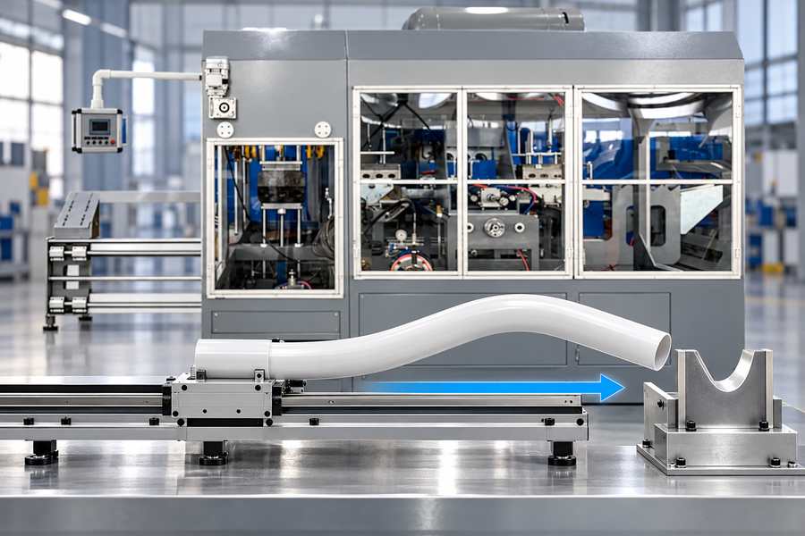
Ejection stroke is the distance a finished PVC bend moves between defined release and clearance positions. It differs from actuator travel, tooling withdrawal, and downstream handling movement.
For purchasing, a useful specification connects that distance to a datum, the finished-part envelope, a release sequence, and repeatable measurements. Without those details, a quoted stroke may not ensure tooling clearance.
What Does Ejection Stroke Mean in a PVC Pipe Bending Machine?
Define the Movement Before Assigning a Number
In a bending application, ejection means moving the formed pipe out of its retained position once the agreed cooling and release steps are complete. Not every machine needs a dedicated ejector.
The quoted configuration might use a pusher, a moving support, another mechanism, or manual removal. Confirm the arrangement before adding an automatic ejection-stroke requirement to the purchase specification.
Four movements can appear similar on a layout but describe different functions: opening a mold, withdrawing an internal support, moving the finished pipe, and transferring that pipe farther downstream.
Only the movement designated as ejection belongs in the ejection-stroke dimension. If the buyer needs discharge to a conveyor, define that additional endpoint rather than silently extending the stroke definition.
Establish a Fixed Datum and Two Pipe Positions
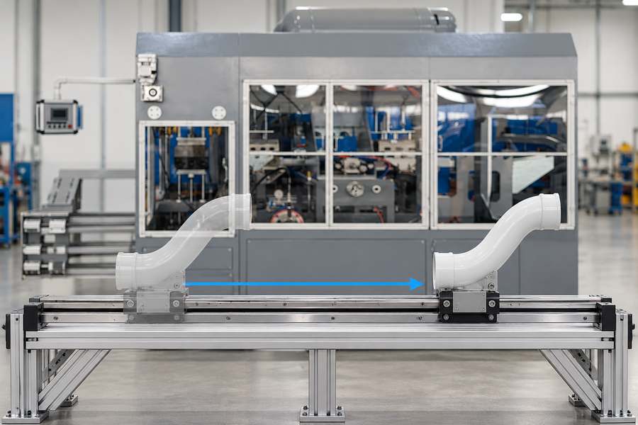
Mark a fixed reference on the machine layout, identify the ejection axis, and indicate its positive direction. The coordinate system must remain unchanged between drawings and trial records.
Define the initial pipe position after the specified tooling has retracted. Then define an endpoint at which the full pipe clears the remaining tooling, or reaches the agreed handoff location.
Measure displacement along the stated axis between these positions. A pusher’s rod extension does not establish pipe movement if there is initial free travel, slipping contact, or a linkage ratio.
The drawing must state what is measured: a reference feature on the pipe, its supporting fixture, or the moving ejector. Record the relationship among them when motion differs.
A controller home indication is not automatically the geometric zero used on the layout. Document any offset so technicians can reproduce the same measurement after adjustments.
Which Pipe Dimensions and Tooling Clearances Determine Ejection Stroke?
Describe the Finished Bend, Not Just the Nominal Pipe Size
Provide the outside diameter, wall thickness, bend angle, centerline radius, straight-leg lengths, and orientation of the bend plane. Include relevant dimensional limits and approved product variants.
The outside diameter influences contact clearance, while leg lengths and bend orientation determine where protruding ends travel. Wall thickness may affect cooling and stiffness without directly defining the path envelope.
A long straight leg can become the limiting obstruction even when the curved section has already left its mold. Conversely, a shorter part can require more movement because of its orientation.
Use a dimensioned finished-part drawing, preferably with the proposed removal direction shown. Where the pipe is not planar, a three-dimensional model may be necessary to locate interference.
Map Every Obstacle Along the Release Path
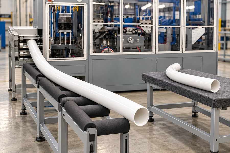
Show the remaining bending mold surfaces, clamps, supports, guides, machine guards, and any proposed receiving equipment. Separate stationary obstacles from components scheduled to withdraw before ejection.
Clearance at the starting and finishing positions is insufficient evidence. Examine the swept volume occupied by the entire bent pipe at intermediate positions along the proposed movement.
Pay particular attention to pipe ends passing near clamp jaws and to curved sections sliding past mold lips. These locations can catch even when the final discharge position looks accessible.
Identify the last interfering edge on the drawing and record how far the designated pipe reference must move before that edge is cleared. This gives the clearance calculation a traceable basis.
For tight passages, mark the smallest predicted gap at several travel positions. This helps reviewers distinguish a true clearance problem from an apparently insufficient final stroke.
Allow for Real Part and Position Variation
The permitted range of bend angle, springback, straight-leg length, and placement can shift the swept envelope. A nominal drawing alone might hide the condition most likely to make contact.
Check boundary parts from the agreed product family, including different orientations where applicable. The largest outside diameter is not automatically the variant needing the greatest ejection displacement.
Document an allowance for measured variation in part position, tooling alignment, and release repeatability. Avoid unexplained extra travel because it may move the pipe beyond the intended receiving location.
Also state whether dimensions describe the pipe immediately after cooling or after further relaxation. The condition used for clearance analysis must match the condition observed during ejection.
How to Determine the Minimum Effective Ejection Stroke
Find the Last Point of Interference
Start with the pipe in its defined initial position and move its complete envelope along the proposed ejection direction. Locate the displacement at which every specified tooling obstruction is cleared.
That value is the geometric clearance movement, not yet the final requested stroke. Add only an allowance supported by dimensional variation, measurement uncertainty, or the agreed receiving requirement.
For a hypothetical calculation, suppose clearance occurs after 125 mm and the documented allowance is 10 mm. The requested effective pipe movement would be 135 mm, measured along the defined axis.
Those numbers are illustrative, not a Yuyu Machinery specification or a general clearance recommendation. The actual values must come from the accepted drawings and trials for the quoted configuration.
If the handoff location is farther away than the clearance location, record both distances. The purchase requirement must make clear which endpoint determines the commanded ejection movement.
Check Whether One Straight Movement Is Possible
A single linear stroke works only when the bend can follow that path without striking tooling or nearby structure. Do not assume the pipe becomes removable merely because clamps open.
If the proposed configuration uses a lift followed by a push, define the travel and endpoint for each axis. Identify the intermediate position at which the next movement becomes possible.
Any rotation, tooling withdrawal, or support movement must appear as a separate action in the sequence. Combining unlike axes into one stroke number makes drawing review and acceptance ambiguous.
Compare Required Movement with Available Travel
Ask for the proposed home position, usable travel, commanded endpoint, and mechanical limits. Confirm that any initial approach movement is excluded from the effective pipe displacement calculation.
Where an actuator contacts the pipe through a lever or support, request the movement relationship over the working range. A nominal actuator stroke cannot substitute for the displacement of the finished part.
Check both ends of travel for contact, overextension, or misalignment. The target is sufficient pipe clearance and controlled placement, not the longest actuator the machine could accommodate.
Stroke length does not describe pushing force or pipe support. If movement deforms the bend, investigate contact area and restraint before increasing the specified travel.
How Do the Ejection Mechanism and Sequence Affect Stroke Requirements?
Confirm the Quoted Release Arrangement
Yuyu Machinery’s pipe bending machine information describes bending-related heating, forming, and cooling arrangements for a featured configuration. It does not establish one universal ejection mechanism or stroke.
Request the configuration drawing showing the proposed contact point, pusher or support location, and pipe orientation at release. Manual extraction and powered ejection require different acceptance language.
If adjustable stops, position feedback, a controlled actuator, or automatic transfer are needed, ask whether each feature is included in the quotation. Do not treat them as standard equipment.
Contact geometry matters as much as distance. A pusher located against an unsupported pipe end may disturb a still-sensitive bend, while poor alignment can create sideways contact during travel.
Where the machine proposal includes a receiving support, compare its position and height with the pipe’s released envelope. A sufficient clearance stroke can still produce an unusable handoff.
For a gravity-assisted or manually completed release, define the point where powered motion ends and the next action begins. Otherwise, acceptance may depend on an unstated operator task.
Verify the Order of Operations
Write the intended sequence explicitly: cooling completion, clamp release, withdrawal of relevant tooling, pipe ejection, and return or transfer. Adapt this order to the actual mechanism and approved process.
Descriptions of positioning, forming, mold retraction, and ejection for belling machines do not prove that the bending machine follows the same sequence. Require a bending-specific confirmation.
Premature travel may drag the pipe against a clamp or internal support. Incomplete cooling can make contact damage easier, while an incorrect home position can reduce the available clearance movement.
When assessing cycle time, separate cooling, tooling withdrawal, ejection, and return intervals. A longer stroke does not establish a proportional cycle-time increase without measured motion speeds and sequence data.
What Belongs in the Ejection Stroke Purchase Specification?
Issue Drawings That Can Be Measured
Supply a controlled drawing of each relevant finished bend, showing critical dimensions, tolerances, bend-plane orientation, and the proposed direction of removal. Identify the drawing revision on the request.
The machine proposal should overlay the part on nearby tooling at the initial, limiting-interference, and final positions. Mark the fixed datum and the same pipe reference at every position.
Include the required receiving position if the ejection function extends beyond tooling clearance. A visual statement that the part is “fully ejected” is not an adequate dimensional requirement.
Use the following checklist to make the technical request comparable across design revisions and to prevent an actuator catalogue dimension from being mistaken for guaranteed pipe displacement.
| Specification item | Information to record in the approved quotation |
| Finished product | Drawing revision, variant range, bend geometry, dimensional limits |
| Ejection definition | Fixed datum, travel axis, positive direction, pipe reference point |
| Clearance requirement | Last interfering feature, minimum displacement, justified allowance |
| Drive arrangement | Proposed mechanism, contact location, actuator-to-pipe movement relationship |
| Travel boundaries | Home position, usable movement, commanded endpoint, mechanical limits |
| Operating sequence | Tooling release steps, start condition, return and transfer actions |
| Receiving interface | Required handoff position, supports, permitted placement variation |
| Verification | Test parts, measurement method, pass criteria, required records |
Identify Scope and Options Before Ordering
Separate essential outcomes from equipment choices. A buyer can specify complete release and a repeatable final position without prescribing an actuator type that conflicts with the proposed tooling.
Ask Yuyu Machinery to identify whether powered ejection, stroke adjustment, position indication, and transfer coordination are part of the quoted package. Record exclusions alongside included functions.
The manufacturer’s customization and service information describes consultation and material testing. Use that discussion to agree on suitable samples, tooling assumptions, drawing approval, and trial coverage.
Specify who supplies representative pipe lengths and bend variants, who approves the reference positions, and which drawing governs changes. Otherwise, later tooling revisions can invalidate an earlier stroke calculation.
If the buyer plans multiple products on shared tooling, require the proposed stroke and endpoint to be checked for every agreed configuration. A single value may not suit every setup.
If product changeover involves a different home offset or stop position, include the adjustment method and verification check in the supplied setup instructions, subject to quotation confirmation.
How to Verify Ejection Stroke During Machine Acceptance
Measure Pipe Movement, Not Only Actuator Extension
Begin with the approved datum and initial position. Measure the same pipe reference again at the defined clearance position and, where applicable, at the agreed handoff position.
A ruler, displacement instrument, fixture reference, or position measurement may be suitable depending on access and required accuracy. State the method and resolution before the test.
Record actuator extension separately where relevant. If pipe movement differs from actuator travel, document initial gaps, linkage motion, part slip, or other features that explain the difference.
Observe intermediate positions for contact with clamps, molds, guides, and receiving supports. A successful final position cannot establish that the pipe traveled without interference along the way.
Use Failure Clues to Diagnose the Actual Cause
Keep inadequate stroke separate from release timing, tooling interference, cooling condition, and incorrect product placement. Increasing travel cannot correct every pipe that sticks or emerges damaged.
| Observed result | What to inspect or measure first |
| Pipe remains partly inside tooling | Actual pipe displacement, defined endpoint, last interfering feature |
| Pipe catches during movement | Swept envelope, clamp opening, tooling withdrawal order |
| Marks or deformation after discharge | Contact location, support geometry, cooling state, pushing alignment |
| Finished position varies between cycles | Starting reference, part slip, repeatability of the proposed mechanism |
| Manual assistance is repeatedly needed | Obstruction location and whether powered release was specified |
| Pipe overshoots the receiving support | Commanded endpoint, travel limits, handoff geometry |
Photograph or mark contact locations where practical, and link each observation to the drawing revision. Do not classify a surface mark as stroke-related without checking the contact sequence.
Record Repeatable Acceptance Evidence
Select trial parts representing the agreed geometric boundaries, not merely whichever pipe is easiest to load. Include each approved tooling setup that changes the release envelope.
For every trial, log the product identification, tooling revision, release settings, initial position, measured clearance displacement, final position, and whether manual intervention or contact occurred.
Run an agreed number of consecutive cycles under stated operating conditions. Record variability rather than reporting only the best movement, and avoid claiming a universal minimum test count.
Acceptance must refer to negotiated criteria: complete tooling clearance, no prohibited contact, acceptable part condition, and final placement within an agreed range. Every criterion needs an observable method.
If a trial fails, record the suspected cause and any adjustment to stroke, tooling, sequence, or support location. Repeat the affected tests using controlled settings and retain both results.
For a recurring release fault, hold the established setup constant while testing a single adjustment, then compare the next cycle with the recorded baseline. Otherwise, a successful retry may provide no clear evidence of which correction resolved the interference.
The signed record should identify the accepted product range, machine configuration, drawing revisions, measured movements, open deviations, and approvals. That evidence makes the ejection-stroke requirement usable during commissioning and later changeovers.