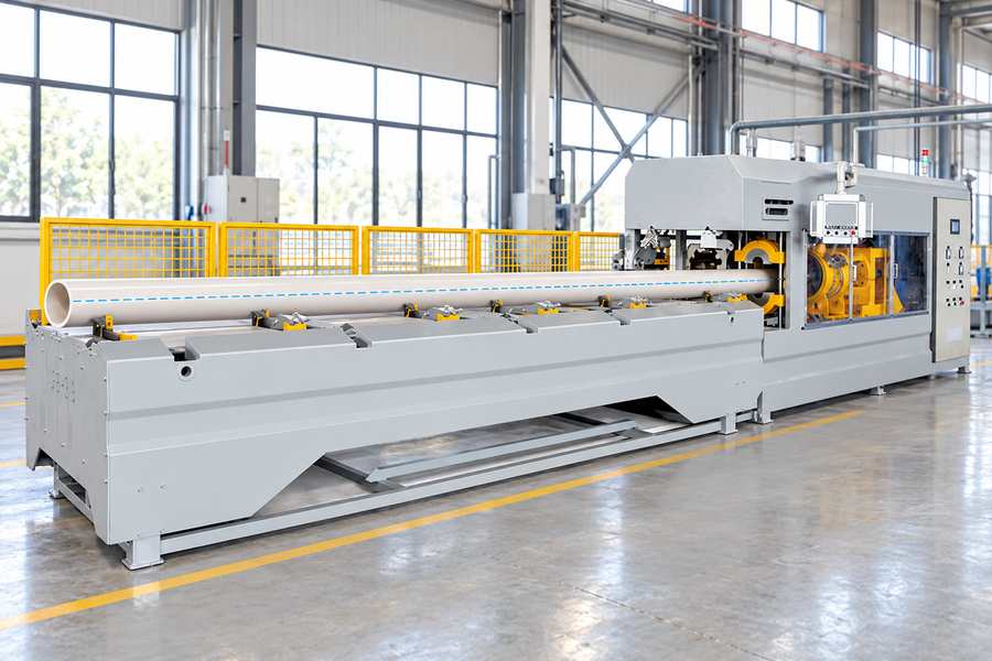
Pipe-centerline adjustment determines whether a thermoplastic pipe enters heating and forming stations on the intended axis. Compare feed, clamp, heater, and mold references instead of assuming one adjustment aligns everything.
These six checks identify mechanisms to inspect, drawing dimensions to request, and test evidence to collect before accepting a machine configured for specific pipes and sockets.
Define the Pipe Centerline Before Evaluating Adjustments
A centerline has little purchasing value unless both parties use the same reference. Ask for a dimensioned layout identifying the machine datum and the intended pipe axis at each station.
For drawing discussions, X can describe the pipe’s longitudinal travel, Y its lateral position, and Z its height. Agree on these directions explicitly; individual drawing conventions may differ.
Specify where each measurement is taken, such as a defined distance from the pipe end or clamp face. A single height dimension does not describe the pipe’s angular orientation.
Where angular alignment matters, measure the axis at two separated cross-sections. The distance between them must be documented so another inspector can reproduce the comparison.
The axis inferred from a pipe’s outside surface can also differ from its nominal geometric center. Ovality, curvature, and unsupported length can influence readings without indicating an incorrectly positioned mechanism.
Yuyu Machinery’s belling machine process overview identifies positioning, clamping, heating, forming, cooling, mold retraction, and ejection. Alignment checks belong at the interfaces between those operations, not only at feeding.
| Drawing reference | What to define | Why it matters during inspection |
| Machine datum | Fixed base plane and lateral reference | Prevents measurements from different starting points |
| Infeed pipe axis | Height, lateral position, measurement station | Separates support settings from feeding errors |
| Clamped pipe axis | Position after jaw closure | Reveals movement caused by clamping |
| Heater axis or opening | Location relative to clamped pipe | Establishes clearance where applicable |
| Mold or mandrel axis | Position and angular relationship to pipe | Distinguishes centering errors from forming-depth errors |
Adjustable Pipe Support Height
Check the Usable Vertical Range
Pipe support height establishes the incoming axis before the clamp takes control. Confirm whether the quoted machine uses adjustable rollers, cradles, or another support arrangement; do not assume all versions have height adjustment.
The required range depends on the actual pipe outside diameters, support geometry, and intended tooling. Request the lowest and highest achievable centerline positions, not merely the adjustment screw travel.
Where several supports carry a long pipe, ask whether their settings are independent. Equal roller elevations do not necessarily give a straight pipe axis when supports have different geometry or loads.
Inspect the locking method and adjustment access. A setting that moves easily but shifts during feeding is not useful, and hidden reference points make routine setup difficult.
Look for Sag and Height Drift
Measure the pipe axis near the clamp after positioning representative straightness and length samples. Repeat after locking the supports and transferring the pipe through the normal feed sequence.
If the pipe nose rises or drops as it enters the clamp, investigate support spacing, overhang, and contact changes before attributing the error to the clamp itself.
Record support positions alongside measurements. Without those settings, a successful trial cannot reliably be reproduced after a changeover or maintenance intervention.
Repeat the height check with the shortest and longest specified pipes where their support conditions differ. An acceptable setup for one length may leave another unsupported.
Lateral Pipe-Centering Adjustment
Examine Guide Movement and Contact
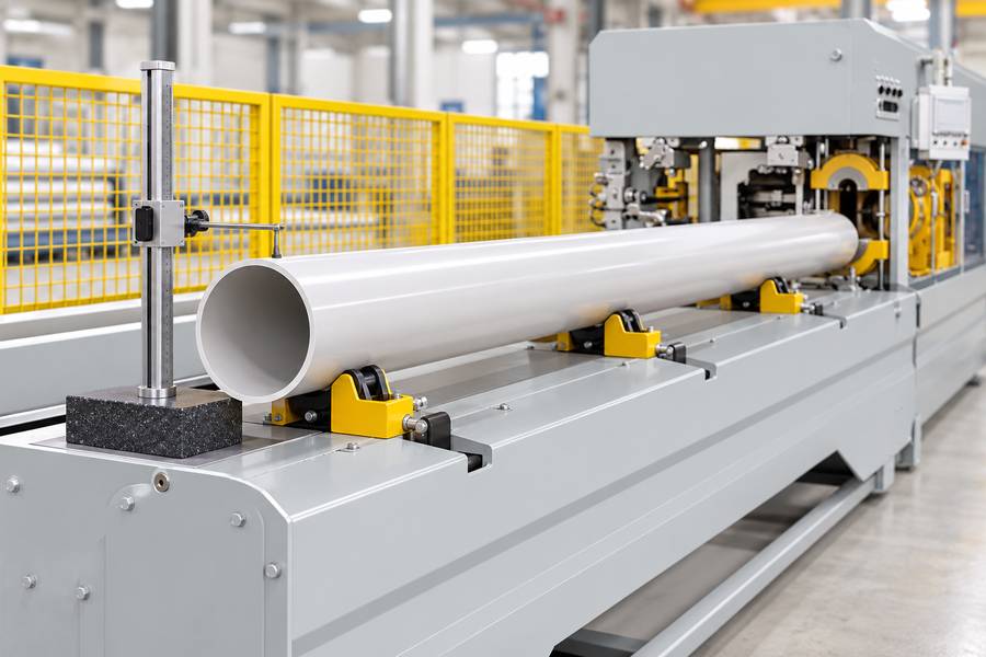
Lateral centering places the pipe within the clamp’s intended capture path. Confirm whether guides, side rollers, or a transfer mechanism can reposition the pipe across the machine width.
Ask whether opposing guides move together around a fixed reference or must be set separately. Independent movement offers flexibility but also permits an unintended centerline shift when only one side changes.
Guide clearance must account for measured outside-diameter variation. Excessive clearance can allow wandering; excessive contact force may resist feeding or deform a relatively flexible pipe.
For a quoted multi-pipe arrangement, request the lane-center spacing and any independent adjustment capability. Shared positioning mechanisms cannot automatically correct different offsets in neighboring lanes.
Check Alignment During Actual Feeding
Measure lateral position before feeding, at the clamp entrance, and after the pipe has stopped. These readings show whether guides establish the axis or merely constrain it temporarily.
Scuff marks on one side, repeated entry corrections, or variable stopping positions are clues worth investigating. They are not proof of a guide defect without checking the incoming pipe.
Request recorded offsets for representative diameter extremes. A setup demonstrated on one nominal pipe size does not establish coverage of every specified size.
Ask operators to identify which guide is the reference during setup. Changing that reference between shifts can create a systematic offset even when the indicated gap remains unchanged.
Pipe-Clamping Centerline Adjustment
Separate Clamp Alignment from Jaw Pressure
The clamp may shift an initially centered pipe as its jaws close. Examine the clamp reference axis and ask which, if any, positioning adjustments are provided in the quoted assembly.
Possible arrangements include repositionable mounts, adjustable jaw carriers, or size-specific contact components. These are items to verify on drawings, not features that should be presumed available.
Compare where the pipe sits with the jaws open and closed. Contact concentrated on one side may indicate mispositioned jaws, unsuitable contact geometry, or dimensional variation in the pipe.
The clamping force must restrain the pipe for the forming operation without unacceptable distortion. Increasing force is not a substitute for correcting the axis or selecting suitable contact surfaces.
Measure Movement After Closure
Take readings at defined points before and after clamping using an agreed measurement method. Note both centerline displacement and any change in pipe cross-section.
Repeat the close-open sequence on the same sample, then assess additional samples within the specified dimensional range. This helps distinguish mechanism repeatability from variation between pipes.
A stable centerline under static clamping still requires confirmation during the operating sequence. Any loaded movement must be assessed against the agreed positioning and socket requirements.
If clamp pads are interchangeable, document the pad identification and seating condition during inspection. Two sets with different contact profiles may locate the same nominal pipe differently.
Heating-Station Centerline Adjustment
Confirm the Heater-to-Pipe Relationship
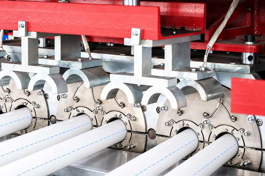
Heating alignment matters where a pipe enters an opening or passes heating surfaces with clearance requirements. Request the heater’s reference geometry and its intended relationship to the clamped axis.
Determine whether the quoted heater assembly has vertical or lateral adjustment, fixed mounting, or size-specific components. Do not mistake the availability of different heating tools for positional adjustability.
Clearance should be checked at the relevant operating position, including insertion and withdrawal where applicable. The drawing must identify both the reference position and any moving assembly involved.
Heating results also depend on time, temperature distribution, rotation where used, and pipe characteristics. Uneven appearance alone cannot isolate centerline error from these other variables.
Verify Position Without Guessing at Heat Quality
For a heater with a defined opening, document the applicable circumferential clearances with the pipe in its specified position. For other arrangements, record the manufacturer-defined alignment references instead.
Repeat positioning checks after several representative cycles, under agreed safe inspection conditions. Note any drift linked to mounting, movement, or thermal operating conditions rather than imposing a universal clearance figure.
Pair alignment records with subsequent socket inspections. If defects remain after alignment is verified, investigate the heating process separately instead of continuing to move the heater.
Check whether a new heater component changes the mounting reference or only the opening geometry. This distinction determines whether replacement requires realignment or just a clearance check.
Forming Mold and Mandrel Centerline Adjustment
Verify Both Offset and Angular Alignment
The forming tool must meet the heated pipe on the intended axis. Request a drawing identifying the pipe reference, tool center, mounting surfaces, and the intended approach direction.
Confirm which alignment directions can actually be corrected: vertical offset, lateral offset, or angular orientation. A tool can have matching center heights yet still approach at an angle.
Ask whether adjustment requires repositioning a mounting plate, adding specified shims, or changing tooling components. The method affects changeover work and the evidence needed after reassembly.
Keep longitudinal forming depth separate from centerline adjustment. Altering insertion distance will not correct a transverse mismatch, and a visually acceptable socket may still require dimensional inspection.
Inspect the Socket, Not Only the Empty Tool
Measure tool-to-pipe alignment before forming, then inspect the produced socket against the specified drawing. Relevant checks may include concentricity, profile dimensions, and localized wall-thickness variation.
An off-center socket can also reflect uneven heating, material variation, or pipe movement during forming. Use the station records to identify the likely source rather than adjusting the mold blindly.
Where tools are removable, repeat alignment measurements after removal and reinstallation. Record shim locations, locating surfaces, fastening conditions, and the reference points needed to restore the setup.
A dimensional defect appearing on the same side of several sockets can direct attention to a fixed offset. A defect that moves between samples calls for additional process checks.
Adjustment Scales, Locking, and Changeover References
Check Whether Settings Can Be Recovered
An adjustment range is only part of the specification. Buyers also need to know how the setting is identified, secured, and restored when production switches to another pipe size.
Inspect whether applicable axes use readable scales, reference marks, stops, recorded dimensions, or another documented setup method. Confirm which of these devices are included in the quoted configuration.
A scale indicates a position; it does not by itself prove accuracy or repeatability. Backlash, loose locking devices, and inconsistent approach direction can all produce different final centerline positions.
If programmable positioning is proposed, identify the controlled axes, saved parameters, homing requirements, and manual corrections. A stored recipe does not necessarily reposition fixed guides or mechanical tooling.
Run a Return-to-Setting Trial
Record the baseline measurements for one pipe configuration, change to another specified size, and restore the first. Measure again without relying solely on displayed settings.
Repeat the trial as agreed, noting adjustments requiring judgment or additional shimming. Keep the initial and restored measurements with the setup sheet used by the operator.
When a restored centerline misses its acceptance limit, document which adjustment moved and whether the error appeared before or after locking. That evidence is more useful than a general changeover-time claim.
Verify Alignment Through an Agreed Acceptance Test
Define the Test Before the Machine Is Built
Machine and pipe variation can be confused unless the test plan establishes reference datums, inspection points, instruments, and allowable deviations. Agree on these details before judging trial results.
Select samples representing the quoted material, diameter range, wall thickness, and relevant pipe lengths. Include actual dimensional measurements so the records show which samples were tested.
Begin with static setup readings, then measure after feeding and clamping. Where practical for the configuration, verify heater and tooling relationships before evaluating formed sockets over repeated cycles.
Separate readings influenced by pipe ovality or curvature from those indicating mechanism displacement. If an axis is derived from several surface measurements, document the method and measurement uncertainty.
| Feature under test | Test condition | Record to retain | Question the evidence must answer |
| Support height | Set, lock, and feed representative pipe | Height and support settings | Does the pipe stay at the intended elevation? |
| Lateral centering | Feed and stop at the clamp | Offset at defined locations | Does the pipe enter without sideways drift? |
| Clamping center | Measure before and after closure | Axis change and pipe deformation | Does clamping displace or distort the pipe? |
| Heating alignment | Check applicable working position | Clearance or reference-axis measurements | Is the heating geometry aligned as specified? |
| Forming alignment | Set tool, form, and inspect socket | Axis readings and socket dimensions | Do setup and finished geometry meet requirements? |
| Changeover references | Change size and restore baseline | Original and restored settings | Can the prior centerline be reproduced? |
Record Failures in a Way That Supports Correction
Each failed check needs the pipe identification, configuration, measurement point, result, agreed limit, and observed condition. Photos or marked drawings can clarify locations that numbers alone cannot describe.
After an adjustment, record the new setting and repeat the affected test. Retain the original failing result rather than replacing it with the final passing measurement.
A passed static check does not establish performance across operating conditions. Acceptance records should identify which dynamic checks were performed and which remain outside the agreed test scope.
Put Centerline Requirements into the Purchase Specification
Request Configuration-Specific Drawings
Provide Yuyu Machinery with pipe materials, measured diameter limits, wall thicknesses, lengths, socket drawings, and the intended single-pipe or multi-pipe arrangement. These inputs determine which adjustments are relevant.
Require a layout identifying all station axes against a common datum. For each applicable adjustment, state the needed direction, usable range, setting method, locking arrangement, and accessibility.
List optional positioning mechanisms separately from included equipment. The six features in this guide are purchasing checks, not a declaration that every Yuyu Machinery belling machine contains all six mechanisms.
Make the Acceptance Agreement Measurable
Define positional tolerances for the actual tooling and product requirements rather than borrowing an arbitrary general figure. Identify who supplies gauges, representative pipes, and the final inspection report.
Set out the number of agreed repeat measurements, changeover configurations, socket dimensions, and pass/fail conditions. Specify how corrective changes will be recorded and retested before sign-off.
Use the service information when discussing setup documentation, inspection responsibilities, and post-installation alignment questions; confirm any requested assistance explicitly in the purchase agreement.
The final technical attachment should connect each required adjustment to a drawing dimension and an acceptance record. That makes disputes about alignment traceable to measurable conditions rather than impressions of socket appearance.