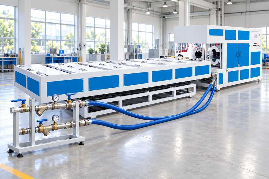
Cooling-water connections should be specified around the actual machine circuits, including supply and return ports, required flow, pressure conditions, and inlet temperature. A published pressure value alone cannot define the site utility.
For procurement, request the supplier’s connection drawing, water-quality requirements, hose routing limits, protective interlocks, and commissioning criteria before releasing the installation plan.
Confirm the Belling Machine’s Cooling Configuration
Identify Which Components Need Water
Start with a cooling-circuit drawing, not a pipe fitting catalogue. The drawing should show each water-cooled assembly, its connection points, and its relationship to the forming sequence.
A mould may contain several passages served by one manifold, or separate branches may feed different components. Buyers should establish the actual arrangement rather than infer it from the machine’s overall dimensions.
Ask which branches receive water throughout production and which operate only during particular stages. This distinction determines peak utility demand and whether individual lines require isolation or flow checks.
The purchase specification should identify machine-integrated passages separately from external supply equipment. A water-cooled machine description does not establish that a pump, chiller, distribution manifold, or connecting hoses are included.
Verify the Selected Model and Cooling Option
Yuyu Machinery identifies the DS250 automatic belling machine as water-cooled and publishes a water-pressure figure of 0.4 MPa. That entry is useful, but incomplete for installation design.
The listed pressure must be clarified: is it measured at the machine inlet, under flowing conditions, or at another reference point? Also request the applicable operating range and measurement conditions.
The published DS250 information does not establish water flow, inlet temperature, connection thread, return pressure, or water quality. None of those values should be derived from the 0.4 MPa entry.
The DS110S, by contrast, offers water or air cooling. Before designing a water service, verify that water cooling is included in the ordered configuration and identify its actual connections.
Yuyu Machinery’s belling machine range includes different models. A utility specification approved for one configuration should not automatically be applied to another.
Specify Cooling-Water Supply and Return Interfaces
Establish Port Details from Approved Drawings
For each connection, request its function, location, orientation, nominal size, and mating interface. A simple inlet-and-outlet label is insufficient where several circuits or manifolds are present.
Connection type matters as much as nominal diameter. Thread form, sealing method, fitting geometry, and access around the port all affect whether site piping can be attached reliably.
Do not select a thread or hose size from common workshop practice. The machine supplier should confirm the exact interface, including any adapters supplied as part of the equipment.
Drawings should distinguish machine-boundary connections from connections between internal assemblies. This prevents the installer from treating an internal service point as the intended plant utility interface.
Define Supply and Return Piping
Identify where the plant supply terminates and where return water is intended to go. The arrangement may involve a closed loop, dedicated cooling equipment, or another approved system.
A return connection cannot be treated as hydraulically unrestricted without evidence. Backpressure affects the available pressure differential and may change circulation through a restricted cooling passage.
Specify where supply and return pressures will be measured. Readings taken at a remote pump or header may differ materially from pressures at the machine during production.
External pipe length, bends, valves, filters, and flexible hoses all introduce resistance. The buyer should account for those losses when comparing the site’s available utility with machine requirements.
| Interface item | Buyer should obtain | Why it matters |
| Supply port | Quantity, location, fitting type, size | Correct plant-side connection |
| Return port | Quantity, location, fitting type, size | Defined return path |
| Supply pressure | Required range and measurement point | Available inlet conditions |
| Return pressure | Allowed backpressure and reference point | Usable pressure differential |
| Flow requirement | Per-circuit demand and concurrent total | Pump and pipe evaluation |
| Inlet temperature | Acceptable range at stated operating conditions | Cooling capacity assessment |
| Scope boundary | Included hoses, valves, adapters, manifolds | Procurement responsibility |
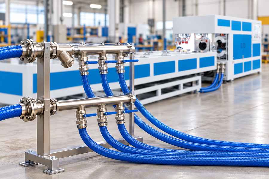
Route Hoses for Operation and Service
A connection can be dimensionally correct yet impractical to maintain. Review hose paths against moving mechanisms, machine guards, access panels, and the space needed to remove fittings.
Confirm hose suitability for the specified water conditions and mechanical exposure. Bend radius, abrasion protection, support spacing, and strain relief should follow the selected hose and fitting requirements.
Avoid routing that forces a hose to carry the weight of external piping or twists the connection during assembly. Where equipment moves, confirm the intended movement envelope with the supplier.
Place isolation points where maintenance personnel can access them without disturbing adjacent services. Record who supplies the hoses, supports, valves, and any necessary connection adapters.
Determine Flow, Pressure Drop, and Inlet Temperature
Keep Flow and Pressure Requirements Separate
Pressure at a supply header does not tell the buyer how much water passes through a mould. Flow depends on the pressure difference across the circuit and its hydraulic resistance.
A machine may receive the stated inlet pressure while return-line restriction reduces the differential available for circulation. Conversely, a larger pressure reading alone does not establish an appropriate flow condition.
Ask the supplier for the required flow through each circuit, the associated pressure conditions, and the intended measurement locations. These values should correspond to the selected equipment and operating sequence.
A shared cooling-water header does not ensure equal circulation: resistance in each individual branch determines how the available water divides during operation. A total-flow reading cannot always demonstrate adequate circulation through every critical passage.
The buyer’s hydraulic review should combine machine-side resistance with external piping losses. It should also consider changes in plant header pressure when other equipment draws water.
Specify Inlet Temperature Against Cooling Duty
Water flow is only part of heat removal. The temperature entering the cooling circuit influences the temperature difference available to extract heat from the forming equipment.
Request an acceptable inlet-temperature range for the actual configuration and duty. Avoid substituting a general plant-water target for a supplier-confirmed machine requirement.
The relevant operating conditions include pipe material, dimensions, socket geometry, and cycle timing. These influence the heat that must be removed before the formed end can be released.
For an engineering estimate, water-side heat removal depends on mass flow, specific heat, and the difference between return and inlet temperatures. Such a calculation requires measured or justified inputs.
A warmer return does not, by itself, prove that the mould is cooled adequately. Product condition, local flow distribution, and the timing of measurements must also be considered.
Cooling duty should be checked against the point in the cycle when the socket must retain its required dimensions, not merely against a water-temperature target measured after production.
Check Concurrent Demand at the Site
A cooling circuit may run continuously while another opens only during a forming step. Combined demand should therefore be established from the actual operating sequence, not simply guessed.
If several branches operate together, the plant must maintain suitable flow and inlet temperature at that concurrent load. Shared headers may experience changing pressure or water temperature.
Request operating conditions for representative high-demand production, including the pipe sizes and cycles the buyer intends to run. A utility assessment based only on idle conditions is inadequate.
Where the plant cannot meet confirmed requirements, identify whether changes to distribution piping or cooling equipment are necessary. Do not presume that a larger connection alone resolves insufficient cooling.
Specify Circuit Distribution, Water Quality, and Drainage
Identify Branches and Control Points
A circuit diagram should show how water enters each branch and rejoins the return. That drawing provides the basis for identifying isolation points, measurement locations, and potential flow imbalance.
Separate adjustment may be appropriate where branches have different hydraulic resistance, but it should not be assumed that every circuit includes its own valve or flow sensor.
Ask whether balancing devices, strainers, or temperature instruments are supplied, optional, or entirely external. The purchase specification should describe the needed function without claiming unverified standard equipment.
Where branches share a common inlet, check whether an adjustment in one branch affects others. This matters particularly when production changes alter which cooling passages are active.
Agree on Water Quality and Wetted Materials
Cooling passages may be vulnerable to deposits, corrosion, or suspended debris. The acceptable water condition depends on the actual wetted materials, passage geometry, and maintenance approach.
Request supplier-approved limits or treatment requirements for relevant water characteristics. Hardness, suspended solids, conductivity, and chemical compatibility may need review, but no universal limits should be imposed without evidence.
Filtration can address particular contaminants, but an arbitrary filter rating may create unnecessary resistance or fail to control the relevant problem. Match treatment decisions to confirmed circuit needs.
The scope should also identify who maintains water treatment and checks its condition. A clean commissioning sample cannot establish how a shared cooling loop will behave over continued service.
Provide Drain, Vent, and Cleaning Access
Air trapped in elevated passages can interfere with circulation and distort pressure readings. Establish how the installed arrangement can be filled and vented using supplier-approved provisions.
Locate low points where water may remain after isolation. Confirm how circuits will be drained for servicing, relocation, or protection against freezing where that risk exists.
Cleaning access is another purchasing question. Determine whether flushing connections or removable strainers are part of the machine, or whether site-installed fittings must provide those functions.
Do not assume a drain valve exists merely because the machine is water-cooled. Show the agreed drain, vent, and isolation points on the installation documents.
Define Monitoring and Cooling-Related Interlocks
Measure Conditions That Reflect Actual Circulation
A pressure gauge at the incoming header confirms only the condition at that measurement point. It does not establish flow through a restricted or closed branch.
For important circuits, discuss whether flow indication, pressure differential, or temperature monitoring is appropriate. Instrument selection should follow the identified failure modes and supplier-confirmed operating requirements.
Measurement points must be accessible and clearly documented. If acceptance relies on a temporary instrument, specify the connection or method needed to take a repeatable reading.
Distinguish equipment furnished with the machine from buyer-requested additions. Neither published cooling mode nor a water-pressure entry proves that individual-circuit sensors are installed.
Agree on Fault Responses Before Commissioning
The operating specification should address loss of water supply, inadequate circulation, abnormal inlet temperature, and excessive return restriction where these conditions are relevant to the configuration.
For each monitored condition, agree whether the required behavior is an indication, an alarm, prevention of another cycle, or a controlled interruption of operation.
Thresholds, delays, and restart permissions must come from an approved design. A buyer should not introduce arbitrary settings that conflict with the forming process or equipment controls.
Ordinary process interlocks protect cooling performance and equipment operation; they do not independently establish personnel-safety functions. Any required safety-related functions need separate definition and validation.
Verify Connections During Commissioning and Acceptance
Inspect and Prepare the Installed Circuits
Begin with the approved connection drawing and the equipment as delivered. Check port identification, hose routing, supports, accessible valves, and the intended return destination.
Confirm that fittings are compatible and assembled according to approved instructions. Installation inspection should also identify avoidable strain, kinks, and locations where leakage could go unnoticed.
Filling, flushing, venting, and leak checking should follow supplier-approved procedures appropriate to the equipment. Record which circuits were prepared and any deviations requiring correction.
Measure Conditions During Representative Production
Record supply and return pressure at the agreed locations while cooling water is flowing. Measurements taken only with closed valves or an idle machine cannot demonstrate operating conditions.
Measure circuit flow where required, along with inlet and return temperatures. When multiple circuits operate together, check whether the utility maintains the agreed conditions across the combined demand.
Production trials should reflect the specified pipe materials, dimensions, and cycle sequence. The acceptance record should connect water readings with the resulting socket condition and agreed product criteria.
If cooling varies, investigate hydraulic distribution, trapped air, water temperature, measurement location, and process timing before adjusting unrelated forming settings. Avoid treating a single pressure reading as the diagnosis.
Different observations point toward different questions for the supplier and site utility team:
- Low flow despite available inlet pressure: Check whether return restriction, branch imbalance, or contamination explains the measured pressure differential.
- Unexpectedly high return pressure: Compare the actual return path and shared-header conditions with the approved piping arrangement.
- Variable inlet temperature: Review cooling equipment performance and simultaneous plant demand before changing the machine cooling cycle.
| Acceptance check | Evidence to record | Agreed basis |
| Connection identification | Installed ports and drawing revision | Approved interface drawing |
| Supply and return conditions | Pressures at defined points during flow | Supplier-confirmed operating requirements |
| Circuit circulation | Flow readings for designated branches | Agreed circuit requirements |
| Water temperature | Inlet and return readings under load | Confirmed temperature criteria |
| Concurrent demand | Measurements with applicable circuits active | Defined production duty |
| Leakage and drainage | Inspection and functional observations | Approved installation procedures |
| Formed-pipe results | Socket inspection under representative operation | Agreed product acceptance criteria |
| Monitoring response | Recorded indication, fault, and recovery behavior | Approved control specification |
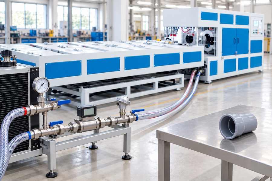
Check Fault Handling and Complete Handover
Demonstrate the agreed cooling-related alarms and responses using approved test methods. Record the observed behavior and confirm that restart requirements match the documented operating sequence.
The final package should contain the approved hydraulic interface drawing, cooling-circuit diagram, confirmed utility conditions, and any required water-quality and maintenance instructions.
Include measurement locations, commissioning readings, instrument identification where relevant, and the operating conditions used for acceptance. These details make future troubleshooting more meaningful than an unsigned checklist.
Before acceptance, resolve differences between drawings and actual connections and identify any remaining buyer-supplied utilities. The documented deliverable is an installation whose interfaces and operating conditions have been verified.