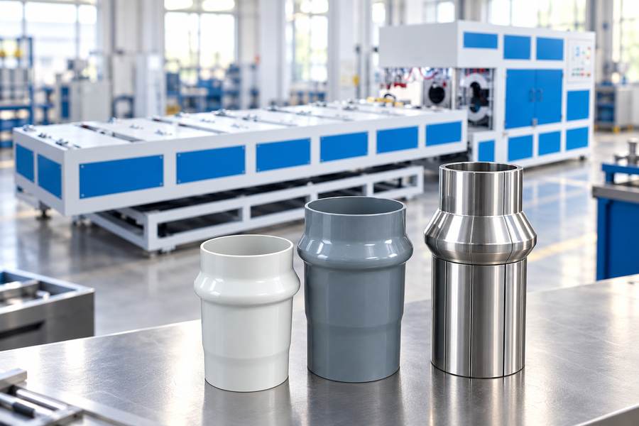
Mandrel surfaces and release details affect socket appearance, dimensional consistency, and removal after forming. Buyers should inspect the specified tooling rather than assume all belling machines use the same mandrel.
These seven checks cover finish, geometry, materials, moving seams, venting, cooling, and alignment. Each links a visible condition to supplier questions, inspection evidence, or a representative forming-and-release trial.
1. Mandrel Surface Finish and Contact Quality
Why Contact Surfaces Matter
The mandrel contacts a pipe end while its material is sufficiently softened for socket forming. Surface defects can transfer marks to the pipe or increase resistance as the tooling separates.
A smooth-looking surface is not necessarily acceptable throughout the forming profile. Small raised edges can be more troublesome than shallow marks because they project into the pipe-contact area.
Inspect the entry region, changes in diameter, grooves, and other accessible contact zones under suitable lighting. Look for scoring, dents, corrosion, machining ridges, embedded residue, and coating damage.
Surface inspection should distinguish intentional tool marks allowed by the approved drawing from damage that changes contact conditions. Buyers should not specify an arbitrary roughness number without considering the pipe material and socket design.
Relate the Finish to Actual Socket Results
A visual examination establishes surface condition, but it cannot prove reliable release. Forming trials should also check for longitudinal drag lines, localized impressions, and material left on the mandrel.
Compare the position of any socket mark with the corresponding tooling surface. This helps distinguish a repeatable mandrel defect from damage introduced during handling or downstream operations.
Ask the supplier to describe how critical surfaces are inspected before shipment and after maintenance. Inspection methods and acceptance limits should follow the agreed tooling specification, not an assumed industry-wide finish.
Useful purchase evidence includes:
- Surface inspection record: Identify the inspected contact regions and any defects requiring correction.
- Agreed finish requirement: State which drawing surfaces have specified texture or condition requirements and how they will be assessed.
- Representative socket samples: Retain results that show whether the selected tooling leaves unacceptable marks during normal release.
2. Lead-In Geometry and Mandrel Profile Transitions
Inspect the Entry and Forming Profile
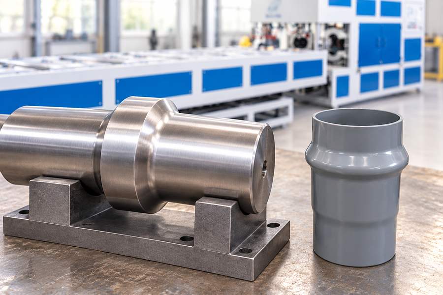
The lead-in guides the heated pipe end toward its forming position. Its shape must suit the pipe approach, while the complete mandrel profile must match the required socket geometry.
Review the transition from the entry surface to each working diameter. Sharp unintended steps, damaged shoulders, and uneven radii may disturb material movement or create concentrated contact during withdrawal.
A step or recess may belong to the specified forming profile. Some shoulders or grooves produce intentional socket features, so inspection must use the approved profile drawing rather than appearance alone.
Check whether the drawing identifies critical dimensions, radii, and transitions clearly enough for manufacturing and inspection. Where information is missing, request clarification before approving tooling.
Evaluate Geometry Against the Release Path
Forming accuracy and removal clearance are related but separate questions. A mandrel might reproduce the intended socket shape yet resist withdrawal if its fixed geometry conflicts with the release direction.
Review the actual release path, including whether the design withdraws directly or uses movable components. Do not prescribe a universal draft angle; the required clearance depends on the socket and mould arrangement.
Compare measured socket dimensions with the agreed pipe-joint requirements. If the pipe shows localized distortion after removal, investigate the profile, temperature condition, and release movement before changing the drawing.
When comparing different models in Yuyu Machinery’s belling machine range, ask for the mould configuration specified for the intended pipe product. A machine category alone does not establish which mandrel profile is supplied.
3. Mandrel Material and Coating Suitability
Identify the Material Behind Each Working Surface
Material selection affects wear behavior, corrosion exposure, mechanical support, and how a mould responds to repeated heating and cooling. Coatings introduce another interface that needs its own inspection criteria.
Separate the base material from a surface treatment in purchase documents. A steel component with plating should not be described as though the plating determines its entire structural performance.
Ask which parts touch softened pipe, which guide collapsible motion, and which provide structural support. These functions may require different material properties and different inspection priorities.
Repeated cycles can expose existing damage or change surface condition. However, the presence of a particular material or coating does not, by itself, establish release performance or a guaranteed service life.
Use Published Information Only for the Applicable Configuration
The published Yuyu Machinery DS250 automatic belling machine information identifies materials for its R-type mould. That information is useful for supplier questions, but it is not a specification for every mandrel.
| Published DS250 R-type mould information | Buyer verification |
| 3CR13 is listed among mould materials | Identify the specific components using it and whether their surfaces contact the pipe. |
| 40Cr is listed for collapsible parts | Confirm which moving pieces use this material and how their contact and guide surfaces are inspected. |
| Other parts are listed as 45# steel with chromium electroplating | Identify the applicable parts, plated regions, and agreed coating inspection requirements. |
The listing does not establish a universal coating thickness, hardness, or allowable surface roughness. Those values, where necessary, belong in the approved design and purchasing documents.
Request material identification for the exact supplied assembly, together with applicable treatment details and a method for resolving mismatches. Keep the record linked to component drawings rather than a generic machine description.
4. Collapsible Mandrel Segment Seams and Movement
Inspect Segment Interfaces in the Forming Position
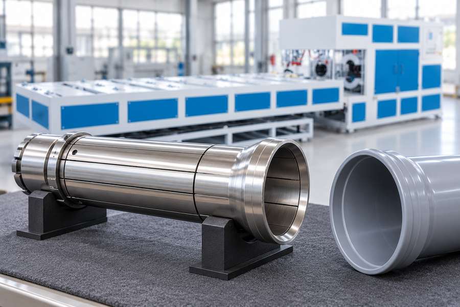
Collapsible designs rely on multiple parts meeting to create a forming surface and then moving away to provide release clearance. Their seams therefore require a different inspection from fixed profile transitions.
Examine the expanded assembly for raised segment edges, uneven joints, unexpected gaps, and offsets. A seam can be mechanically functional while still leaving a visible line on the formed socket.
Not all segment boundaries can be completely invisible. The acceptance question is whether their geometry and resulting socket appearance meet the approved requirements for the intended product.
Ask the supplier how the expanded position is established and checked. Repeatability matters because a joint that appears level during static inspection may shift after several operating cycles.
Confirm Retraction and Clearance
Observe the full collapse and return sequence, where the supplied tooling uses this mechanism. Each segment should follow its intended path without binding, striking adjacent parts, or remaining partially expanded.
Inspect accessible guides and mating surfaces for wear or contamination that could obstruct movement. Excessive play may also change the forming profile, even when collapse remains possible.
The DS250 product information describes an external-pressure chamber or a vacuum-pump arrangement with collapsible moulds. Confirm which option and associated tooling are included in the actual offer; do not treat alternatives as simultaneous standard equipment.
During representative trials, record any seam impressions, withdrawal resistance, incomplete release, or evidence of contact after collapse. A successful single cycle is weaker evidence than repeated observations under agreed production conditions.
Keep the assessment tied to the supplied mechanism. Buyers should not assume every belling machine uses collapsible segments or that a particular segment arrangement is interchangeable between socket profiles.
5. Venting and Pressure-Equalization Features Where Applicable
Determine Whether Separate Provisions Are Needed
Air trapped between a pipe surface and its tooling can matter in some forming arrangements. Pressure differences may also influence separation, depending on the mould design and process sequence.
These effects do not mean every mandrel needs vent holes. A supplier may achieve the necessary forming and release behavior through the overall tooling geometry and process arrangement.
Distinguish pressure or vacuum used to form a socket from a dedicated vent or equalization feature near the mandrel surface. A forming circuit applies force to shape the pipe; a local vent addresses trapped air at a particular interface.
Ask the supplier to identify any release-related air passages on the specified drawing. If none are used, request an explanation of the intended separation method rather than demanding an unverified feature.
Inspect Any Supplied Passages and Release Details
Where openings or channels are provided, review their location, accessibility, and susceptibility to blockage. Their edges should not introduce unwanted impressions on critical socket surfaces.
Consider whether residue, moisture, or routine cleaning could alter passage condition over time. The supplier should identify inspection points and suitable maintenance instructions for the actual arrangement.
A release difficulty does not automatically prove insufficient venting. Check the profile clearance, tool and pipe temperatures, contact-surface condition, and withdrawal movement before assigning the cause.
Acceptance trials should therefore observe the finished socket and the release sequence, not merely confirm that a passage exists. Do not assume lubricant or air-assisted ejection is supplied unless specified.
6. Cooling Behavior and Thermal Release Conditions
Understand the Pipe-Mould Temperature Relationship
Cooling changes the pipe’s stiffness and dimensions while the socket remains in contact with its tooling. The resulting contact forces can change as the pipe and mould follow different thermal paths.
Premature release may allow features to deform before they are stable. Waiting longer, however, does not universally reduce friction because contraction can increase contact with certain mould surfaces.
Different socket regions may cool differently because wall thickness, surface contact, and local geometry vary. A single observation near the mould may not represent the complete pipe-wall condition.
For this reason, buyers should ask which conditions govern release readiness for the specified material and socket profile. Do not substitute a universal temperature or cooling time for validated process requirements.
Verify the Release Sequence Under Repeated Cycles
Ask whether the supplied control sequence relies on elapsed time, sensor information, or another defined condition. A timer setting indicates process duration; it does not directly measure every socket surface temperature.
During trials, inspect both immediate release behavior and socket dimensions after the agreed assessment condition. Record sticking, ovality, deformation, and surface marks where these are relevant acceptance characteristics.
Compare observations across representative operating cycles, including periods after the mould reaches its normal working thermal condition. Changes between initial and repeated cycles can reveal a temperature-dependent release issue.
The trial record should state pipe material, relevant product geometry, cooling method, and the agreed acceptance criteria. Without those conditions, a release result may be difficult to reproduce.
Cooling specifications for the machine utility system are a separate procurement subject. Here, the key requirement is evidence that the actual mould and release sequence preserve the intended socket geometry.
7. Mandrel Alignment and Service Condition
Check the Installed Position, Not Only the Loose Tool
Mandrel geometry can be accurate on the inspection bench yet perform poorly after installation. Position relative to the pipe centerline, clamping arrangement, and forming motion affects contact distribution.
Misalignment may create heavier contact on one side, producing asymmetric socket features or increased withdrawal resistance. Review the installed assembly rather than relying solely on component dimensions.
Inspect locating faces, mounting interfaces, supporting parts, and accessible guides. Look for looseness, contamination, damaged reference surfaces, or wear that could change the working position.
Ask how alignment is established following tooling removal or replacement. The supplier should identify the approved reference features and inspection method without assuming that adjustment procedures are identical across machines.
Agree on Inspection and Functional Acceptance
A purchasing checklist should distinguish material and drawing conformity from actual forming performance. Both matter: documents cannot prove clean release, and a sample socket cannot identify every hidden tooling issue.
Use representative pipe material, dimensions, and socket profiles for the agreed trial. Define what will be measured, which surface defects are unacceptable, and how repeated release behavior will be recorded.
| Inspection topic | Recommended acceptance evidence | Question for the supplier |
| Contact finish | Inspected critical surfaces and evaluated socket appearance | Which contact defects trigger rework or rejection? |
| Lead-in and profile | Approved drawings, relevant dimensions, and formed socket measurements | Which transitions and dimensions are controlled? |
| Materials and coatings | Component-level material and treatment records | Which specifications apply to the supplied parts? |
| Collapsible seams, if fitted | Expanded-position inspection and repeated movement observations | How are joint condition and complete retraction verified? |
| Venting or equalization, if fitted | Drawing review and functional checks | How are passages inspected and kept clear? |
| Cooling and release | Representative-cycle observations and socket dimensions | What condition authorizes release for this application? |
| Alignment and service | Installed-position inspection and maintenance documentation | How is correct positioning restored after servicing? |
The table is a proposed procurement framework, not a claim that every listed feature comes standard. Remove nonapplicable rows only after confirming the proposed mould arrangement and release method.
Secure Service Information and Final Deliverables
Routine service can alter the conditions established at acceptance. Cleaning methods, disassembly, part replacement, and reinstallation should therefore preserve contact surfaces, alignment, and moving clearances.
Ask which wear indications require closer inspection and how damaged coatings or segment faces are handled. Repair suitability should be determined from approved component requirements, not improvised surface treatment.
Before tooling approval, obtain a defined set of records:
- Approved drawings: Identify the forming profile, critical dimensions, contact regions, and relevant moving interfaces.
- Material documentation: Match base materials and surface treatments to the components actually supplied.
- Inspection results: Record surface, profile, segment, and installed-alignment checks where applicable.
- Trial acceptance records: State the tested pipe products, observed release behavior, and measured socket characteristics.
- Service instructions: Explain applicable cleaning, inspection, removal, reinstallation, and replacement requirements.
The purchase specification should identify who provides each document and which criteria must be satisfied before acceptance. That makes later service comparisons possible without assuming the mould will remain unchanged indefinitely.