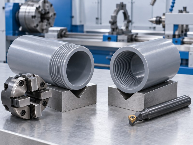
Internal threading requires a tool that fits inside the bore, reaches the full thread length, and clears chips without striking the opposite wall. External threading requires access around the outside diameter and restraint against cutting torque. Both need support that holds the pipe round and aligned without distorting the finished thread.
The main difference is where the cutting and support systems compete for space. An internal support can assist some external operations, while internal threading must leave that bore accessible to the cutting tool.
Define the Connection Before Choosing the Tool
“Internal” and “external” identify the cutting surface, not the complete thread specification. The intended joint still determines profile, dimensions, engagement, and inspection.
Prepare a connection drawing containing:
- Material grade and actual pipe dimensions.
- Thread designation and governing drawing or standard.
- Parallel or tapered geometry.
- Pitch, lead, number of starts, and hand.
- Usable engagement length and permitted runout.
- Sealing method and mating-component identification.
- Dimensional limits and inspection requirements.
| Thread Location | Drawing Requirement | Tooling Consequence |
| Internal | Finished bore, thread diameters, and access length | Tool and holder must fit within the available bore |
| External | Finished outside thread diameters and surrounding clearance | Cutting head must clear clamps, shoulders, and adjacent features |
| Either location | Profile, pitch, lead, taper, and thread length | Determines cutting geometry and motion coordination |
Yuyu’s plastic pipe threading equipment and customization page describes internal and external processing with custom thread shapes. Submit the finished joint drawing when requesting a configuration; a nominal pipe size alone cannot define the required tools.
Check the Remaining Wall at the Thread Root
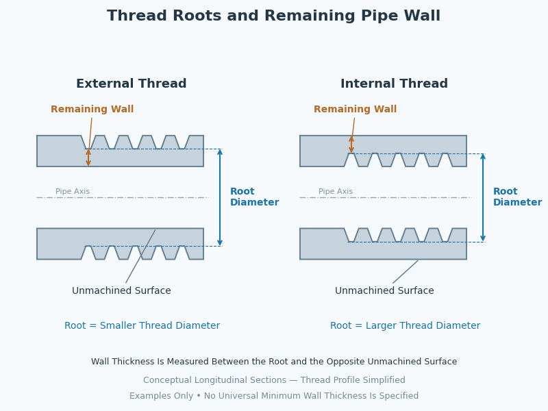
Thread cutting removes material from the pipe end. External cutting reduces the outside diameter locally; internal cutting enlarges the bore locally. Review the resulting section before arranging clamps or approving a sample.
For a concentric circular section at a specified axial station:
| Operation | Geometric Wall Check |
| External thread | (External thread root diameter − Bore diameter) / 2 |
| Internal thread | (Outside diameter − Internal thread root diameter) / 2 |
For an internal thread, the root corresponds to the larger thread diameter. For an external thread, it refers to the minor diameter. Confirm the drawing convention before calculating.
These expressions check geometry, not allowable pressure or joint strength. Include incoming wall variation, eccentricity, taper, and any preparation cut when assessing the actual minimum section.
- Confirm that the pipe or prepared end is approved for threading.
- Check the most demanding location along a tapered thread.
- Avoid assuming the machined end retains the original pipe rating.
- Use the pipe-system requirements to establish application suitability.
Match External Tooling to the Pipe-End Clearance
External threads may be cut with dies, chasers, or a suitable single-point arrangement. The selected system determines whether the pipe rotates, the cutting head rotates, or coordinated relative motion creates the thread.
Confirm the following:
| Tooling Item | Requirement to Resolve |
| Cutting profile | Match the specified flank, crest, root, and pitch |
| Head envelope | Clear the pipe shoulder, clamps, and other end features |
| Entry condition | Define end squareness, chamfer, and any diameter preparation |
| Cutting length | Reach the full usable thread without exceeding permitted runout |
| Release sequence | Withdraw without damaging the completed thread |
Yuyu lists the DS60-TA automatic thread cutting machine for V-thread processing and the DS250-TS automatic thread cutting machine for T-thread processing. These profile descriptions do not independently confirm every internal or external application.
Ask the supplier to show the proposed head and its clearance on your end drawing. Where several pipe sizes are ordered, identify which cutters and holders are shared and which require replacement.
Give Internal Tools Enough Clearance And Stiffness
An internal tool must fit through the entrance while retaining space for the cutting edge, holder, and chip flow. A tool that fits the nominal bore can still interfere after allowing for bore variation or local ovality.
Review the internal setup against:
- Minimum available bore diameter.
- Toolholder diameter and cutting-edge projection.
- Required reach and unsupported overhang.
- Full thread length and permitted exit space.
- Holder clearance during entry, cutting, and withdrawal.
- Chip removal route inside the pipe.
Keep Reach Separate From Cutting Length
The tool may project farther than the thread length because its holder cannot approach the end face closely enough. Record the actual unsupported distance, not just the requested engagement length.
A larger holder can improve stiffness but reduce bore clearance. A shorter overhang can help stability but may require a different clamping layout. Resolve those constraints together.
When discussing custom internal threading configurations, provide the bore limits and end-access drawing alongside the outside diameter. Do not treat internal threading as an external head with its rotation reversed.
Position Supports Without Blocking the Cutting Surface
Both operations need pipe alignment and restraint against cutting loads. The support arrangement changes because the active surface changes.
| Support Function | External Threading | Internal Threading |
| Hold the pipe | Grip away from the external cutting envelope | Leave bore entry and tool travel clear |
| Preserve roundness | Internal backing may be considered where compatible | External support may be considered around the end |
| Resist torque | Match grip to the actual rotating or stationary arrangement | Restrain the pipe without squeezing the bore closed |
| Support long stock | Align supports with the cutting axis | Align supports with the internal tool axis |
| Release the product | Avoid scraping the finished outside thread | Avoid distorting the freshly cut bore thread |
Supports must follow the actual machine design. Neither an internal mandrel nor an external sleeve is automatically required, and either can introduce interference if positioned incorrectly.
Check the Pipe After Unclamping
A thread can gauge differently while the pipe is squeezed in the fixture. During trials, compare the relevant diameter and roundness in the released condition using the approved inspection method.
If alignment changes when a long pipe is loaded, inspect roller height and support spacing before increasing clamp force. The chuck should not be used to pull misaligned stock into position.
Control Cutting Conditions Around the Actual Material
Internal processing offers less visible access to the cutting zone, but it is not universally slower than external processing. Tool design, material, thread geometry, reach, and chip removal determine suitable conditions.
Establish a trial record containing:
- Pipe material, batch, and prepared dimensions.
- Tool identity, profile, and condition.
- Relative rotational speed and feed coordination.
- Pass sequence, where applicable.
- Support settings and tool overhang.
- Chip removal and any approved cooling method.
- Released-thread inspection results.
Plan Chip Removal Before Approving the Head
External chips are generally easier to observe, although a surrounding head can still trap them. Internal chips can remain in the bore, contact the tool again, or obscure the finished profile.
| Observation | Check Before Changing the Program |
| Chips packed inside the bore | Extraction access and the tool’s evacuation path |
| Repeated marks on the thread | Retained chips, cutting-edge condition, and tool contact |
| Stringy material wrapped around the holder | Material response, chip path, and cutting conditions |
| Poor finish late in a run | Accumulation, tool wear, and thermal changes |
| Debris left after unloading | Cleaning sequence and accessible inspection areas |
Define when chips are removed and how cleaning is performed. Avoid cleaning methods that damage thread crests or introduce an unapproved chemical.
Inspect Internal And External Threads With the Correct References
Use inspection documents matching the thread designation. Internal threads generally require the specified plug-type inspection arrangement; external threads require the specified ring-type arrangement or another approved method. The appropriate gauge is determined by the thread system used.
The first-piece record should cover:
- Material and drawing revision.
- Prepared end dimensions and thread location.
- Profile, pitch or lead, hand, and taper where applicable.
- Usable engagement length and runout.
- Required gauge result under the defined conditions.
- Crest damage, burrs, chips, and visible cracks.
- Relevant dimensions after release from the fixture.
A mating component can reveal obvious interference but does not replace a specified gauge. Likewise, a passing dimensional check does not demonstrate sealing or application performance.
Where the connection seals on a separate gasket or face, inspect that feature independently. Do not assume that every threaded joint seals through thread contact alone.
Define the Changeover And Supply Scope Before Ordering
Changing from outside to inside threading can involve more than exchanging cutting inserts. Confirm the complete conversion against the product matrix.
| Supply Item | What the Quotation Should Identify |
| Cutting tools | Internal and external profiles, holders, and size coverage |
| Workholding | Jaws, inserts, supports, and contact locations |
| Machine capability | Motion, bore access, reach, and required clearances |
| Chip handling | Extraction components and cleaning sequence |
| Controls | Product recipes and coordinated motion requirements |
| Inspection | Required gauges, methods, and acceptance documents |
| Trials | Representative materials and thread combinations |
Approve samples from both operations if both are ordered. Keep their setup records separate, including tool reach, support arrangement, and released inspection results.
A useful inquiry combines the pipe specification, both thread drawings, mating-component details, and required output. With those inputs, the supplier can confirm a tooling and support arrangement that suits the actual connection rather than the nominal pipe size.