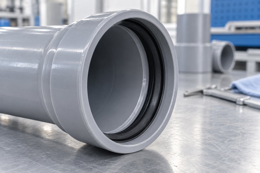
Rieber belling is a pipe socket-forming process in which the sealing gasket is incorporated into the socket during manufacture. The gasket is positioned on a forming mandrel, and the heated pipe end is shaped around that assembly. After the socket has been formed and cooled, the mandrel withdraws while the gasket remains retained in the pipe end. The result is a socket supplied with its sealing element already installed.
For pipe manufacturers, the important distinction is the relationship between the gasket and the forming operation. A conventional ring-seal socket can be formed first and fitted with a separate gasket afterward. In Rieber belling, the intended gasket participates in the forming arrangement. That changes the tooling, loading sequence, quality checks, and production controls needed to make a reliable finished connection.
How Rieber Belling Differs from Other Socket Processes
A plain socket relies on the connection design specified for that pipe system, commonly including solvent-cement assembly for appropriate PVC products. A conventional gasketed socket contains a groove that receives a suitable sealing ring after forming. A Rieber socket retains the intended gasket as part of the manufacturing sequence rather than depending on a later ring-installation step.
These arrangements should not be selected by appearance alone. The finished socket drawing, pipe application, mating spigot, seal specification, and required joint tests establish what the production system must achieve. A machine able to form a visible ring groove is not automatically equipped for integrated-gasket belling.
When reviewing Yuyu Machinery’s belling machine options, identify the required connection process explicitly. This helps separate a request for a conventional ring socket from one requiring compatible gasket loading, forming tooling, and verification of the integrated seal.
Gasket Retention Is Different from Joint Restraint
A retained gasket is held in its intended socket location. Axial restraint is the ability of a completed joint to resist separation under the relevant loads. These are different functions. An integrated sealing ring should not be described as providing axial restraint unless the complete joint has a specific restraint design and the necessary qualification.
This distinction matters when communicating with buyers. A joint can provide sealing while still requiring the installation provisions defined by the pipe system. The belling process does not replace project design, installation instructions, or the product’s pressure and loading requirements.
The Main Stages of a Rieber Belling Cycle
The detailed sequence depends on the machine, tooling, pipe material, and seal design. Manufacturers should work from the approved process documentation rather than a generic temperature or cycle-time table. The following stages describe the main functions that must be coordinated.
1. Identify and Prepare the Pipe and Gasket
Confirm the pipe dimensions, material specification, socket drawing, and gasket identity before production. Inspect the pipe end for the incoming condition required by the process, including cutting quality, cleanliness, and any specified end preparation. Keep gasket batches identifiable and protected from contamination or damage.
Qualify the gasket as part of a specific tooling-and-socket combination before introducing it into the production sequence. Similar overall diameters do not make different gasket profiles interchangeable. Establish how operators verify the selected seal, and what the machine does if the correct component is unavailable or cannot be positioned properly.
2. Load the Gasket onto the Forming Tool
The gasket is placed at the specified position on the mandrel. Position and orientation matter because the ring has to remain correctly located as the pipe end advances through the forming sequence. Depending on the supplied equipment, loading may involve manual assistance or an automatic feeding mechanism.
Verification should address more than simple presence. A ring can be present but incorrectly oriented, incompletely seated, or damaged. The required checks depend on the seal geometry and machine design. Any sensor or interlock claim should describe an actual feature of the offered machine and its demonstrated capability.
3. Heat the Pipe End Under Controlled Conditions
The required section of pipe is heated sufficiently for the approved forming operation. Uniformity around the circumference and through the relevant wall section helps the pipe respond consistently. The heating recipe must match the material, diameter, wall thickness, socket length, and thermal characteristics of the equipment.
A heater setpoint is not the same as the pipe’s actual forming condition. Do not apply one temperature from a general description to every product. Establish and validate the process window through trials that include final socket dimensions, seal condition, and the required joint performance checks.
4. Form the Socket around the Tool and Seal
The softened pipe end is brought over the mandrel and the positioned gasket. The machine’s approved forming sequence establishes the socket profile. Depending on the process design, vacuum or external pressure may help the pipe conform to the forming arrangement. The exact stages and timing must match the supplied tooling.
Alignment and controlled movement are important throughout this operation. An irregular incoming end, an incorrect ring position, or an unsuitable thermal condition can interfere with consistent forming. Record abnormal motion, incomplete travel, and process alarms instead of clearing them repeatedly without investigation.
5. Cool, Release, and Inspect
Cooling stabilizes the formed pipe end sufficiently for release under the approved procedure. The mandrel then withdraws, leaving the gasket retained in the socket. Handling must preserve the newly formed geometry and avoid damage to the sealing surface or socket mouth.
The socket should be inspected after the conditioning required by the product’s quality plan. Check dimensions and the visible gasket condition, then apply the specified functional tests. An apparently complete cycle does not by itself establish that the finished joint meets its requirements.
Benefits of Integrating the Gasket During Manufacture
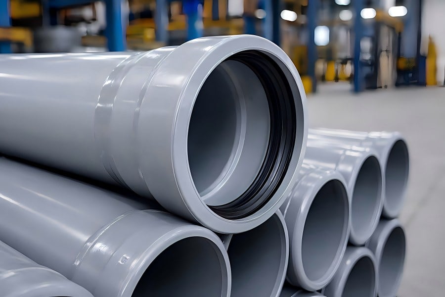
The practical benefits depend on successful control of the complete process. They should be expressed as design and workflow advantages rather than universal promises of zero leakage or zero scrap. The pipe manufacturer still needs compatible components, qualified settings, and a documented inspection system.
Controlled Seal Location at the Factory
Integrating the gasket during socket manufacture allows its location to be established within the production process. The manufacturer can verify the supplied socket and seal as an identified assembly. This reduces reliance on a separate ring being selected and inserted later, although it does not eliminate the need to check the finished product.
Factory control is most useful when ring identity, tooling, process settings, and inspection results remain traceable. Without that link, a retained gasket can make an error harder to correct after forming. Preventing the wrong component from entering the cycle is therefore a central quality requirement.
Reduced Handling of Loose Sealing Components
A socket supplied with its gasket installed can simplify the handling of sealing parts during storage and installation. There is no separate loose ring to pair with that socket at the point of assembly. Packaging and transport must still protect the gasket and prevent debris from collecting inside the pipe end.
The benefit should not be overstated as permission to ignore installation checks. The assembler must still inspect the socket and mating spigot, follow the approved preparation and lubrication instructions where applicable, and achieve the specified insertion position.
A Defined Socket-and-Seal Manufacturing Combination
The process encourages the pipe producer to treat the socket, seal, mandrel, and operating recipe as a compatible set. That makes qualification more explicit. It also gives quality personnel a clearer basis for identifying which component or process revision was used for a production batch.
Changes to gasket design, material, tooling, or pipe formulation should therefore trigger a review of the approved combination. A replacement component that looks similar may change loading behavior, forming response, or sealing performance. Manage those changes through the factory’s qualification procedure.
Equipment Requirements Beyond a Conventional Beller
A Rieber belling arrangement needs the same basic functions of pipe handling, heating, forming, cooling, and control, but it must also accommodate the integrated gasket sequence. The practical requirements should be specified for the intended products rather than assumed from the machine name.
| Equipment area | Requirement to define | Verification during evaluation |
| Pipe handling | Compatible length, diameter, mass, and incoming condition | Stable positioning through repeated cycles |
| Heating | Validated recipe for material, wall, and socket geometry | Accepted sockets after specified conditioning |
| Gasket loading | Correct component, orientation, and position | Repeated loading with the intended seal |
| Forming tooling | Compatible mandrel and approved socket profile | Dimensional and functional qualification |
| Cooling and release | Stable geometry and controlled tool withdrawal | No unacceptable deformation or visible seal damage |
| Controls and records | Recipe identification, alarms, and production traceability | Demonstration of supplied functions and records |
Tooling Compatibility and Changeover
Specify tooling by pipe size, wall range, socket drawing, and seal design. Confirm the complete set of inserts, supports, loading parts, and other components needed for each product. A change of diameter may require more than replacing the mandrel if the seal-loading arrangement or pipe guides also need adjustment.
Evaluate a representative transition during the trial. Include preparation, tool handling, recipe selection, stabilization, and first-piece approval in the timing. Keep an approved setup sheet that identifies the complete combination, so a familiar pipe diameter does not lead to selection of an incompatible ring or tool.
Utilities and Machine Layout
Review the electrical supply, compressed air, cooling water, and vacuum provision where applicable to the offered design. Confirm flow, pressure, temperature, and connection requirements in the machine documentation. A stable process can depend on utilities that are shared with other equipment in the factory.
Allow space for gasket storage and replenishment, tool handling, inspection, and maintenance access. Check the layout with the actual pipe length and transfer direction. A compact machine footprint does not describe the full operating area needed for loading, unloading, and servicing.
How to Qualify Socket and Seal Quality
Use the approved product drawing to identify dimensional checks for the socket bore, depth, profile, roundness, and wall distribution. Inspect the gasket’s visible orientation, seating, and condition without disturbing it. Where destructive examination is required, identify the sample clearly and keep it out of saleable production.
The role of a sealing gasket is easier to understand when the complete mating interface is considered. The pipe spigot, socket, seal, and assembly procedure determine the result together. Dimensional inspection is necessary, but any specified leakage, pressure, vacuum, or other joint test must also follow the applicable method.
Record pipe batch, gasket batch, tooling identification, recipe revision, production time, and test results. If a seal is damaged or incorrectly positioned, follow the approved nonconformance procedure. Do not assume that an integrated gasket can be replaced without affecting the socket or that a repaired joint remains qualified automatically.
Common Production Issues to Investigate
Repeated ring-loading interruptions may arise from component variation, contamination, orientation problems, or an unsuitable adjustment. Confirm the incoming gasket condition and the mechanical setup before changing the forming recipe. An adjustment that masks a feeding issue may create a different problem at the socket.
Uneven sockets require a review of incoming pipe geometry, heating consistency, alignment, forming conditions, and cooling. Visible damage to a seal requires attention to its loading, contact surfaces, and the forming and withdrawal sequence. Investigate from recorded evidence rather than assuming that every defect has the same temperature-related cause.
Keep rejected samples associated with their process records. Compare them with accepted samples from the same product and tooling. That comparison can help identify whether the issue begins before forming, during the thermal cycle, or during handling after discharge.
Maintain Traceability When Components Change
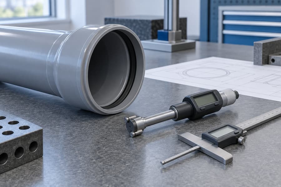
Keep an approved reference sample and the associated inspection report for each qualified socket-and-seal combination. When a drawing, gasket batch specification, or tooling revision changes, review which previous results remain applicable. Record the decision and identify any repeat testing required before routine production resumes. This creates a practical link between purchasing, production, and quality personnel, especially when several sizes use similar-looking components.
Specify Rieber Belling Around the Finished Joint
An equipment inquiry should include the pipe material, actual diameter range, wall specifications, cut lengths, intended output, socket drawings, and approved gasket information. Add the inspection and functional test requirements, expected changeover frequency, and available factory utilities. These details define the production task more clearly than a request for an automatic machine alone.
Ask for a trial that demonstrates repeated accepted production with the intended pipe and seal, including loading, forming, cooling, and discharge. Yuyu Machinery can review these requirements through its technical inquiry channel. The objective is a controlled socket-and-gasket process that the factory can reproduce, inspect, and maintain across its planned product range.